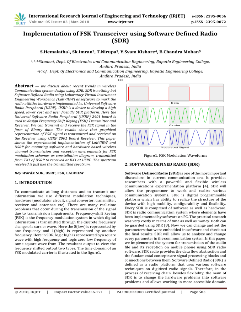
International Research Journal of Engineering and Technology (IRJET) e-ISSN: 2395-0056 Volume: 05 Issue: 03 | Mar-2018 p-ISSN: 2395-0072 www.irjet.net Implementation of FSK Transceiver using Software Defined Radio (SDR) S.Hemalatha1, Sk.Imran2, T.Nirupa3, Y.Syam Kishore4, B.Chandra Mohan5 1, 2, 3,4Student, Dept. Of Electronics and Communication Engineering, Bapatla Engineering College, Andhra Pradesh, India 5Prof. Dept. Of Electronics and Communication Engineering, Bapatla Engineering College, Andhra Pradesh, India ---------------------------------------------------------------------***--------------------------------------------------------------------- Abstract — we discuss about recent trends in wireless Communication system design using SDR. SDR is nothing but Software Defined Radio using Laboratory Virtual Instrument Engineering Workbench (LabVIEW) as software to mark the radio utilities hardware implemented i.e. Universal Software Radio Peripheral (USRP). USRP is a device to develop a high speed, lower cost and user friendly SDR platform. Here the Universal Software Radio Peripheral (USRP) 2901 board is used to design Frequency Shift Keying (FSK) Transmitter and Receiver. We can transmit and receive the FSK signal in the form of Binary data. The results show that graphical representation of FSK signal is transmitted and received on the Receiver using USRP 2901 Board Receiver. This paper shows the experimental implementation of LabVIEW and USRP for mounting software and hardware based wireless channel transmission and reception environments for FSK modulation schemes as constellation diagram, transmitted from TX1 of USRP to received at RX1 at USRP. The spectrum received is just like the transmitted spectrum. Key Words: SDR, USRP, FSK, LABVIEW 1. INTRODUCTION To communicate at long distances and to transmit our information we use different modulation techniques, hardware (modulator circuit, signal converter, transmitter, receiver and antennas etc). There are many real-time problems that occur during the transmission of the signal due to transmission impairments. Frequency-shift keying (FSK) is the frequency modulation system in which digital information is transmitted through the discrete frequency change of a carrier wave. Here the 0(low) is represented by one frequency and 1(high) is represented by another frequency. Here in SDR, logic high is represented by a square wave with high frequency and logic zero low frequency of same square wave from .The resultant output to view the frequency shifted output two types. The time domain of an FSK modulated carrier is illustrated in the figure1. © 2018, IRJET | Impact Factor value: 6.171 | Figure1. FSK Modulation Waveforms 2. SOFTWARE DEFINED RADIO (SDR) Software Defined Radio (SDR) is one of the most important discussions in current communication era. It provides researchers with a powerful and flexible wireless communications experimentation platform [4]. SDR will allow the programmer to work and realize various communication systems. SDR is digital programmable platform which has ability to realize the structure of the device with high mobility, configurability and flexibility. Every SDR is comprised of software as well as hardware. SDR is radio communication system where elements have been implemented by software on PC. The practical research was very costly in terms of time as well as money. Both can be guarded using SDR [8]. Now we can change and set the parameters that were embedded in software and check out the final results. SDR will allow us to analyze and change every parameter in the communication system. In this paper, we implemented the system for transmission of the audio file and its reception on mobile phone using SDR radio software. SDR radio provides the data flow abstraction and the fundamental concepts are signal processing blocks and connections between them. Software Defined Radio (SDR) is defined as a radio platform that uses various software techniques on digitized radio signals. Therefore, in the process of receiving chain, besides flexibility, the main of SDR is to change the hardware problems into software problems and allows working in more accessible domain. ISO 9001:2008 Certified Journal | Page 583 International Research Journal of Engineering and Technology (IRJET) e-ISSN: 2395-0056 Volume: 05 Issue: 03 | Mar-2018 p-ISSN: 2395-0072 www.irjet.net SDR is divided into two subsystems: One is hardware defined subsystem that consists of antenna and ADC, the other is Software Defined subsystem. For efficient working, the device should satisfy the following three conditions: 1. The antenna should be capable to operate at the frequency of all radio signals. 2. ADC and DAC should operate at the sampling rate greater than twice the Frequency of signal. 3. To handle the signal processing of all radio signals, the software subsystem should have enough processing power. In SDR, hardware defined subsystem consists of wideband radio which takes the portion of the spectrum and converts it to IF before the digitization process. The software defined subsystem receives the digitized wideband signal and then send to the down converters to isolate the carrier. Finally demodulation is performed. Programmable devices are combined to compose the software defined subsystem, such that connection between them is fast enough to transfer the DSP data. Figure3. USRP-2901 Module The USRP-2901 has two local oscillators, one for the transmit (Tx) channels and one for the receive (Rx) channels. While different frequencies can be used for the Tx and Rx channels, the two Tx channels are locked to the same frequency, and the two Rx channels are locked to the same frequency. The operating range is from 70MHz-6GHz and bandwidth of 56MHz. 4. LABVIEW SOFTWARE Figure2. Block Diagram of SDR 3. UNIVERSAL SOFTWARE RADIO PERIPHERAL (USRP): Universal Software Peripheral (USRP) is Universal hardware that can be accessed using software which is SDR Radio software on LabVIEW platform. Hardware mainly consists of three parts. First one is the radio frequency (RF) frontend which transmits and receive the radio signals. Second one acts as a bridge between analog block and digital block [2]. All signal processing is done within the third block in software form. The analog RF signal can be received or transmitted by antennas or directly connected via SMA connectors to the RF frontend called Daughter boards [7]. USRP has various daughter boards which are vary from each other depending on their operating frequency. These daughterboard are connecting to the motherboard and acts as RF frontend of USRP. Here we use USRP 2901. The physical appearance of USRP 2901 is shown in below. © 2018, IRJET | Impact Factor value: 6.171 | LabVIEW is a graphical programming language developed by National Instruments. The basic building block of LabVIEW is the virtual instrument (VI). Conceptually, a VI is analogous to a procedure or function in conventional programming languages. Each VI consists of a block diagram and a front panel. The block diagram describes the functionality of the VI, while the front panel is a top level interface to the VI. The construct of the VI provides two important virtues of LabVIEW: code reuse and modularity. The graphical nature of LabVIEW provides another virtue: it allows developers to easily visualize the flow of data in their designs. NI calls this as Graphical System Design [1]. Also, since LabVIEW is a mature data flow programming language, it has a wealth of existing documentation, toolkits, and examples which can be leveraged in development. LabVIEW can integrate with wide variety of Hardware devices, including NI USRP. Lab VIEW consist two types of programming. Dataflow Programming: The programming language used in LabVIEW, also referred to as G, is a dataflow programming language. Execution is determined by the structure of a graphical block diagram on which the programmer connects different function-nodes by drawing wires. These wires propagate variables and any node can executes soon as all its input data become available. Since this might be the case for multiple nodes simultaneously, G is inherently capable of parallel execution [6]. Multiprocessing and multithreading hardware is automatically exploited by the built-in scheduler, which multiplexes multiple OS threads over the nodes ready for execution. Graphical Programming: LabVIEW ties the creation of user interfaces. Each VI has three components: a block diagram, a front panel, and a connector panel. The last is used to ISO 9001:2008 Certified Journal | Page 584 International Research Journal of Engineering and Technology (IRJET) e-ISSN: 2395-0056 Volume: 05 Issue: 03 | Mar-2018 p-ISSN: 2395-0072 www.irjet.net represent the VI in the block diagrams of other, calling VIs. Controls and indicators on the front panel allow an operator to input data into or extract data from a running virtual instrument. However, the front panel can also serve as a programmatic interface. Thus a VI can either be run as a program, with the front panel serving as a user interface, node onto the block diagram, the front panel defines the inputs and outputs for the given node through the connector pane. This implies each VI can be easily tested before being embedded as a subroutine into a larger program. 5. FSK Implemented Results: We designed the FSK system in LabVIEW with the help of different communication blocks and signal processing blocks. Those blocks are available in the LabVIEW software. The system was designed along with the transmitter and receiver of the FSK system. Figure shows the diagram of the transmitter of the FSK system: Filter length 6 Samples per Symbol 16 FSK deviation 1.00k TX Filter Gaussian TX Antenna TX1 of USRP In the front panel of the FSK system the outgoing constellation graph for 15 bits is shown along with two frequencies of the signal are shown. The waveform graph shows the generated FSK signal. The different parameters of the transmitter are shown. Fig. 5 shows the front panel of the transmitter. Figure 5. Front panel of FSK Transmitter with parameters Similarly, the block diagram of the receiver could be drawn according to the system requirements. Fig. 6 shows the block diagram of the FSK receiver. Figure 4. Block diagram of FSK Transmitter with USRP blocks TABLE I. PARAMETERS USED AT TRANSMITTER Parameter at Transmitter Value used Carrier Frequency 915MHz IQ Rate 100k Gain at Transmitter Antenna 25 Alpha value 0.5 © 2018, IRJET | Impact Factor value: 6.171 Figure 6. Block diagram of FSK Receiver with USRP blocks | ISO 9001:2008 Certified Journal | Page 585 International Research Journal of Engineering and Technology (IRJET) e-ISSN: 2395-0056 Volume: 05 Issue: 03 | Mar-2018 p-ISSN: 2395-0072 www.irjet.net TABLE II. PARAMETERS USED AT RECEIVER Parameter at Transmitter [1]Hans-Petter Halvorsen, 2016-09-07, M.sc. University College of Southeast Norway, introduction to LabVIEW. Value used Carrier Frequency 915MHz IQ Rate 100k Gain at Transmitter Antenna 25 Alpha value 0.5 Filter length 6 Samples per Symbol 16 TX Antenna REFERENCES [2]Lab Based Learning with NI USRP, and LabVIEW Communication Student Lab Manual, Bruce A. Black. [3]Introduction to USRP, Department of Electrical and Computer Engineering Ben-Gurion University of the Negev. [4]Software Defined Radio Receiver, The University of California at Riverside Department of Electrical Engineering, John Cortes, Varoon Malhotra. RX2 of USRP The Front panel of FSK Receiver is shown in below: [5]Bitter, Rick et al "LabVIEW Features" LabVIEW Advanced Programming Techniques Boca Raton: CRC Press LLC, 200 [6]VI Lab manual, Faculty of Engineering and Technology SRM University, Tamilnadu. [7]NI USRP Hands on sp manual, ni.com/usrp, National Instruments Corporation. [8]Software Defined Radio, John Cortes, Varoon Malhotra Faculty Advisor: Yingbo Hua. [9]GNU RADIO and USRP, Electrical and Computer Engineering, Cleveland State University, Harshil Mehta, Raag Kharadi. Figure 7. Front panel of FSK Receiver with parameters 6. CONCLUSION With the help of SDR kit, the implementation of FSK system becomes very simple because it replaces all hardware that is used in the traditional communication system with software. SDR has a lot of potential for implementing the emerging wireless applications. We demonstrated the usability of SDR to implement the communication system. The FSK Transmitter and Receiver systems implemented here give the concept of Software Defined Radio with the help of USRP 2901 as a hardware tool and LabVIEW as a software tool. We implemented a communication system with LabVIEW software with USRP and we successfully transmit the Digital data from USRP board and received it on the same USRP board at different time. Hence it is clear that one can implement other communication systems using SDR and analyze the performance. Therefore using SDR it is possible to design prototype of the Communication systems and possible to verify the real time performance of the system. A lot of research is being done on the SDR in different applications to make it available for commercial use. © 2018, IRJET | Impact Factor value: 6.171 | ISO 9001:2008 Certified Journal | Page 586

![Chapter 3 Overview and Basics of software Defined Radios[1]](http://s2.studylib.net/store/data/005704797_1-e5ea591c4f19f0cf490d196d110ed37b-300x300.png)
