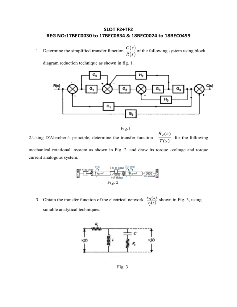
SLOT F2+TF2 REG NO:17BEC0030 to 17BEC0834 & 18BEC0024 to 18BEC0459 1. Determine the simplified transfer function C s of the following system using block Rs diagram reduction technique as shown in fig. 1. Fig.1 2.Using D'Alembert's principle, determine the transfer function 𝜃2 (𝑠) 𝑇(𝑠) for the following mechanical rotational system as shown in Fig. 2. and draw its torque -voltage and torque current analogous system. Fig. 2 3. Obtain the transfer function of the electrical network suitable analytical techniques. Fig. 3 vo ( s ) shown in Fig. 3, using vi ( s ) 4.Simulate and Infer the first order system C(t) analytical expression in matlab for the given input a) unit step input b) Ramp input and c) Parabolic input. Also, derive the analytical expression for the system time response c(t) for the same. 5. Determine the transfer function using Mason’s Gain formula REG NO: 18BEC0503 to 18BEC2011, 18BML0082 to18BML0106 & 19BML0005 to 19BML0067 1. Find the transfer function, X 3 (S ) , for the translational mechanical system shown in F ( s) fig.1. And draw its force-voltage and force current analogous system. fig.1 2. Determine the transfer function using Mason’s Gain formula fig. 2 3. 4. Simulate and Infer the second order system C(t) analytical expression in matlab for the given input a) unit step input b) Ramp input and c) Parabolic input. Also, derive the analytical expression for the system time response c(t) for the same. 5. Construct the signal flow graph for the given transfer function


