International Journal of Trend in Scientific
Research and Development (IJTSRD)
International Open Access Journal
ISSN No: 2456 - 6470 | www.ijtsrd.com | Volume - 2 | Issue – 4
A Review on Performance Enhancement of Catalytic Conveter by
Making Geometrical Changes
1
Vinayak Shukla1, Prof. Yogesh Tembhurne2
Research Scholar, Bhabha Engineering & Research Institute, RGPV Bhopal, MP, India
I
2
Professor, Bhabha Engineering & Research Institute
Institute,, RGPV Bhopal, MP, India
I
ABSTRACT
Now a days the global warming and air pollution are
big issues in the world. The 70% of air pollution is
due to emissions from an internal combustion engine.
Catalytic monolith converters have been used for
nearly four decades to reduce the toxicity of exhaust
gases from the internal combustion engine powering
automotive/machines The harmful gases like NOX,
CO, unburned HC and particulate
culate matter increases the
global warming, so catalytic converter plays an vital
role in reducing harmful gases, but the presence of
catalytic converter increases the exhaust back pressure
due to this the volumetric efficiency will decrease and
fuel consumption
mption is higher. So analysis of catalytic
converter is very important. The scarcity and high
demand of present catalyst materials necessitate the
need for finding out the alternatives. So this paper is
based on to find the possibility regarding to reduce
emission and converted into high rate.
Keywords: Catalytic convertor, CFD, Substrate,
Porous zone, Emission
1. INTRODUCTION
An exhaust system is a gadget utilized as a part of
vehicle to control emanations by changing over
dangerous results from ignition (happening in the I.C
engine) to less harmful substances by moving
synthetic responses through catalyzed. The responses
changee contingent on the sort of substrate or catalyst
altered. Albeit exhaust systems are essentially utilized
as a part of exhaust system in cars, trains, planes,
generator sets, mining hardware, and other motor
fitted gadgets. They are likewise utilized on ssome
wood stoves to control discharges. There are three
sorts of exhaust system 1) reduction catalytic
converter 2) oxidization catalytic converter 3) threethree
way catalytic converter (TWC). An oxidation catalyst
is a gadget that is set on the end of fumes pipe of an
auto. The oxidation catalyst is the second phase of the
catalytic converter. It diminishes the hydrocarbons
and carbon monoxide by oxidizing them over a
platinum and palladium impetus1.
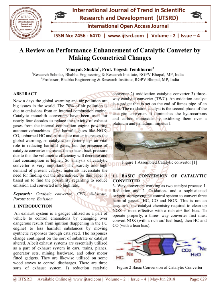
Figure 1 Assembled Catalytic convertor [1]
1.1 BASIC CONVERSION OF CATALYTIC
CONVERTER
3- Way converters working as two catalyst process: 1.
Reduction and 2. OxidationOxidation and a sophisticated
oxygen storage/engine control system to convert three
harmful gasses- HC, CO and NOX. This is not an
easy task: the catalyst
lyst chemistry required to clean up
NOX is most effective with a rich air/ fuel bias. To
operate properly, a three- way converter first must
convert NOX (with a rich air/ fuel bias), then HC and
CO (with a lean bias).
Figure 2 Basic Conversion of Catalytic
Cataly Converter
@ IJTSRD | Available Online @ www.ijtsrd.com | Volume – 2 | Issue – 4 | May-Jun
Jun 2018
Page: 629
International Journal of Trend in Scientific Research and Development (IJTSRD) ISSN: 2456-6470
1.2 DANGERS OF POLLUTANTS
Without the redox process to filter and change the
nitrogen oxides, carbon monoxides, and hydrocarbons
into less harmful chemicals, the air quality (especially
in large cities) would reach a harmful level to the
human being.
Nitrogen oxides- these compounds are in the same
family as nitrogen dioxide, nitric acid, nitrous oxide,
nitrates, and nitric oxide. When NOx is released into
the air, it reacts with organic compounds in the air and
sunlight, the result is smog. Smog is a pollutant and
has adverse effects on children's lungs.
Carbon monoxide- this form of CO2 is a harmful
variant of a naturally occurring gas. Odorless and
colorless, this gas does not have many useful
functions in everyday processes.
the rate of surface reaction with the catalyst first
increases and then become stable. [1]
S.P. VENKATESAN ET AL 2017 have study on
emission control of catalytic convertor by using
copper oxide. The main aim of this work is to
fabricate system, where the level of intensity of toxic
gases is controlled through chemical reaction to more
agreeable level. This system acts itself as an exhaust
system; hence there is no needs to fit separate the
silencer. The whole assembly is fitted in the exhaust
pipe from engine. In this work, catalytic converter
with copper oxide as a catalyst, by replacing noble
catalysts such as platinum, palladium and rhodium is
fabricated and fitted in the engine exhaust. [2]
1.3 METHODOLOGY
VLADIMIR LOZHKIN ET AL 2017 The purpose
of investigation was the development of mathematic
model of catalysis process in the mode of heat
rejection (“discharge”) of phase change storage device
and substantiation of high efficiency of cleaning from
harmful substances and possibility of device
arrangement in the engine compartment of a bus
instead of noise suppressor using calculation method
proceeding from experimental data of converter
operation in the city cycle. [3]
Emission control is one of the biggest challenges in
today's automotive industry. Emission control can be
achieved either by controlling combustion or by
treating the exhaust gas. The latter is comparatively
easier since there is less or no need to modify the
engine itself. One such after treatment method is the
use of catalytic converter. But, the 3-way converter is
expensive due to use of both platinum and
palladium/rhodium. One of the alternatives is the use
of selective catalytic reduction, i.e., reduction of a
particular mission based on the type of the engine
used. The flow distribution across the monolith frontal
area depends on the geometry of a specific design of
inlet diffuser
A.K. SHARMA ET AL 2016 A catalytic monolith
converter usually comprises several hundred or
thousands of channels. Mathematical modeling that
seeks to resolve the coupled transport phenomena
mass, momentum, species and heat on a discretechannel scale is a computationally challenging task. In
this context, they present an efficient approach to
overcome the difficulties in the modeling of a
monolith converter. Then study the computational
efficiency of the reduced model for monoliths
comprising O (104 ) channels. The computational
penalty for reduced model is much less as compared
to the full model, making it a possible candidate for
detailed monolith simulations.[4]
II.LITERATURE REVIEW
YOUNG-DEUK KIM ET AL 2009 in this case, the
active metal distribution along the length of the
converter may influence its performance. The optimal
design for the optimal axial distribution of the catalyst
was determined by solving multi-objective
optimization problems to minimize both the CO
cumulative emissions during the FTP-75 cycle, and
the difference between the integral value of a catalyst
distribution function over the monolith volume and
Hydrocarbons- inhaling hydrocarbons from gasoline,
household cleaners, propellants, kerosene and other
fuels can cause death in children. Further
complications can be central nervous system
impairments and cardiovascular problems.
For analyzing the catalytic convertor the various
researches have been study some of these are
explained here.
YUGAL KISHORE ET. AL 2017 carried out a 3D
CFD analysis on three way monolithic converter on
the basis of it various conclusions have been drawn.
The rates of conversion of NO, CO, C3H6 are the
function of temperature. On increasing temperature
@ IJTSRD | Available Online @ www.ijtsrd.com | Volume – 2 | Issue – 4 | May-Jun 2018
Page: 630
International Journal of Trend in Scientific Research and Development (IJTSRD) ISSN: 2456-6470
total catalytic surface area over the total monolith
volume. [5]
THUNDIL KARUPPA RAJ.R ET AL, 2008
analyzed that the design of catalytic converter has
become critical which requires a thorough
understanding of fluid flow inside the catalytic
converter. In this paper, an attempt has been made to
study the effect of fluid flow due to geometry changes
using commercial CFD tool. The study has been
conducted assuming the fluid to be air. The numerical
results were used determine the optimum geometry
required to have a uniform velocity profile at the inlet
to the substrate.[6]
KARVOUNIS & ASSANIS, 1993 Developed a finite
element code to solve the flow field through the inlet
diffuser, the ceramic brick and the nozzle sections of
the catalytic converter for different flow rates and
channels hydraulic diameters and investigated the
effect of non-uniform inlet flow distribution on the
conversion efficiency of the catalytic converter. They
predicted the reactant concentration across the
honeycomb’s outlet based on the velocity distribution
at the inlet. However, the lower the hydraulic
diameter of the channels, the higher the conversion
efficiency and the pressure drop which can be
decreased by shortening the catalytic converter
monolith.[10]
MINGCHEN ET AL, 2008 Analyzed that a
modeling approaches to the design optimization of
catalytic converters is presented. The first step of the
optimization is the model assisted sizing of catalysts.
The second step deals with the flow optimization of
the catalyst converter under the given geometric
restraints. The substrate is modeled as porous media,
where viscous and in it all resistances are specified
via empirical formula. With the help of the CFD tool,
the flow in the converter can be optimized using
appropriate boundary layer control methods.[7]
CHEN ET AL. 2004 utilized a 3D CFD flow
modeling and a heterogeneous reaction model of the
catalytic converter. They calculated the pressure and
the velocity field with incorporating the flow
resistance within the monolith substrate. They
concluded that the flow field is influenced by the
monolith substrate resistance for a specific geometry
and Reynolds number. Moreover, the flow uniformity
at the front face increased with increasing cell density
of the monolith and decreased when increasing the
flow Reynolds number.[11]
CHAKRAVARTHY ET AL., 2003 Utilizing multidimensional channel model. It was recorded that the
ignition behavior can be dramatically affected by flow
recirculation at the inlet of the substrate which lead to
high flow misdistribution especially at lower exhaust
temperatures. The study concluded that flow nonuniformity effects were more significant with
increasing flow temperature. In addition, the pressure
drop distribution remained constant and was
dependent on the recirculation pattern at the front face
of the monolith.[8]
LIU ET AL. 2001 performed an experimental and a
numerical study on the reverse flow catalytic
converter for a natural gas/diesel dual engine. The
simulation involved a 1-dimensional single channel
model to monolith substrate. They concluded that the
conversion efficiency of CO and HC was improved
for the reverse flow catalytic converter for low inlet
temperature and light engine load only when the
catalytic converter initial temperature is high enough
given that the converter initial temperatures was
varied from 694 K to 919 K.[12]
EKSTROM
AND
ANDERSSON
2002
Experimentally investigated the pressure drop across
the monolith brick of the catalytic converter. They
investigated different types of bricks with different
cell density, coating and wall thickness. They did not
include combustion in their experimental work and
used cold and hot air flow instead. They developed an
empirical model that could predict the pressure drop
with good agreement with experimental data and
previous models and can be used for 1-D and 3-D
CFD simulations. They found that the main sources of
pressure drop are viscous and inertial effects.[9]
BENJAMIN ET AL. 2001 simulated the flow
distribution within the catalytic converter. They
considered the entrance effects on the flow to
accurately calculate the pressure drops. They
concluded that treating the flow within a single
channel as one-dimensional laminar flow under
predicts the effect of flow misdistribution. Moreover,
incorporation of pressure-drop improved the peak
velocity predictions at the middle of the monolith of
the catalytic converter.[13]
SHAMIM ET AL. 2002 developed a numerical
simulation to predict the performance of the three-
@ IJTSRD | Available Online @ www.ijtsrd.com | Volume – 2 | Issue – 4 | May-Jun 2018
Page: 631
International Journal of Trend in Scientific Research and Development (IJTSRD) ISSN: 2456-6470
way catalytic converter. The model incorporates heat
conservation and chemical reaction sub model with
oxygen storage mechanism and it showed that the
conversion efficiency was improved when operating
under rich oxygen content. [14]
BELLA ET AL. 1991 investigated the effect of flow
uniformity on the conversion efficiency in their 3D
model discussed earlier. When the flow was nonuniform, it became concentrated in the central region
of the honeycomb which resulted in non-uniformity of
the chemical reaction in the catalytic converter that
caused noble metal depletion and lower conversion
efficiencies.[15]
D. REICHERT ET AL,2009 present paper on study
of the reaction of NOx and soot on Fe2O3 catalyst in
excess of O2.This paper presents characteristics of a
new catalytic converter based on ferric oxide (αFe2O3) in relation with NOx and soot reduction in
emission.[18]
STEFFEN WAGLOEHNER ET AL 2012 present
paper on study on the mechanism of the oxidation of
soot on Fe2O3 catalyst. For the removal of soot from
the exhaust of diesel engines so called diesel
particulate filters (DPF) are currently applied. These
filters operate with high efficiency by forcing the
exhaust to flow through their porous walls. In this
paper we conclude a scheme of global reactions
describing the mechanism of the catalytic soot
oxidation on Fe2O3. [19]
NARENDRASINH R. MAKWANA ET AL 2013
present paper on development and performance
analysis of nickel based catalytic converter. There are
several types of problems associated with noble metal
based catalytic converter. These factors encourage for
the possible application of non-noble metal based
material such as nickel as a catalyst. They have used
Nickel as the oxidizing agent because of its
nonpoisonous nature, low cost and availability makes
it preferred carrier in oxidation from the stationary
pollution sources.[20]
G. C. KISKU, ET AL 2014 present paper on
catalytic converter based on non-noble material. This
paper review problems associated with noble metal
based catalytic converter. Catalytic converter may be
due to factors converter meltdown, carbon deposit,
catalyst fracture and Poisoning. The converter
becomes too hot and melts inside so that the small
particles come apart on the inside. The broken pieces
can move around and get in position to plug up the
flow of exhaust through converter. This meltdown is
caused by converter having too much work to do. [21]
2.1 COMPARITIVE SUMMARY OF LITERATURE REVIEW
AUTHOR’S
YUGAL KISHORE ET. AL 2017
CONCLUSIONS
S.P. VENKATESAN ET AL 2017
The rates of conversion of NO, CO,
C3H6 are the function of temperature.
On increasing temperature the rate of
surface reaction with the catalyst first
increases and then become stable.
The main aim of work is to fabricate
system, where the level of intensity of
toxic gases is controlled through
chemical reaction to more agreeable
level.
System acts itself as an exhaust system;
hence there is no needs to fit separate
the silencer.
@ IJTSRD | Available Online @ www.ijtsrd.com | Volume – 2 | Issue – 4 | May-Jun 2018
Page: 632
International Journal of Trend in Scientific Research and Development (IJTSRD) ISSN: 2456-6470
A.K. SHARMA ET AL 2016
G. C. KISKU, ET AL 2014
NARENDRASINH R. MAKWANA ET AL
2013
Study the computational efficiency of
the reduced model for monoliths
comprising O (104 ) channels.
The computational penalty for reduced
model is much less as compared to the
full model, making it a possible
candidate for detailed monolith
simulations.
Catalytic converter may be due to
factors converter meltdown, carbon
deposit, catalyst fracture and Poisoning.
The converter becomes too hot and
melts inside so that the small particles
come apart on the inside.
They have used Nickel as the oxidizing
agent because of its nonpoisonous
nature, low cost and availability makes
it preferred carrier in oxidation from the
stationary pollution sources
Table 2.1 Comparative analysis of literature review
III. CONCLUSION
As this is a well-known fact that the world is facing
serious problems like global warming acid rain etc.
due to heavy emissions emitted from automobiles and
industries. So this becomes a special area of interest
for engineers and scientist to reduce the emissions
which causes such serious problem.
Manufacturing and testing of catalytic convert
is a costly affair which involves great deals of
time and money to perform the testing of
working of catalytic converter
But using simulation software like Ansys
gives us an opportunity to investigate the
performance of catalytic converter for even
very small dimensional changes without any
great cost involved.
Increasing mass flow rate the pressure drop
increases linearly.
Increasing substrate length improves the
performance of converter.
The results obtained from CFD are reliable to
one which s obtained by experimental setup
with appreciable amount of minimal error.
REFERENCES
1) Yugal Kishore et. al CFD analysis of three way
monolithic catalytic converter using Ansys 14.5r,
International Journal of Mechanical And
Production Engineering, Volume- 5, Issue-11,
Nov.-2017.
2) S.P. Venkatesan et al I.C. Engine emission
reduction by copper oxide catalytic converter.
Materials Science and Engineering 197 (2017)
012026 doi:10.1088/1757-899X/197/1/012026
3) Vladimir Lozhkin et al Catalytic Converter with
Storage Device of Exhaust Gas Heat for City Bus.
Transportation Research Procardia 20 ( 2017 ) 412
– 417
4) A.K. Sharma et al Validity and scalability of an
asymptotically re duce d single-channel model for
full-size catalytic monolith converters Applied
Mathematics and Computation 281 (2016) 186–
198
5) Young-Deuk Kim Optimal design of axial noble
metal distribution for improving dual monolithic
catalytic converter performance Chemical
Engineering Science 64 (2009) 1373 – 1383
6) Thundil Karuppa Raj.R and Ramsai.R “Numerical
Study of Fluid Flow And Effect of Inlet Pipe
Angle In Catalytic Converter Using CFD”, School
@ IJTSRD | Available Online @ www.ijtsrd.com | Volume – 2 | Issue – 4 | May-Jun 2018
Page: 633
International Journal of Trend in Scientific Research and Development (IJTSRD) ISSN: 2456-6470
of Mechanical and Building Sciences, VIT
University, Vellore– 632 014,Tamil Nadu,
INDIA.
7) Ming Chen, Karen Schirmer “A modeling
approach to the design optimization of catalytic
converters of I.C. Engines” PROCEEDINGS OF
ICEF03: 2003 Fall Technical Conference of the
ASME Internal Combustion Engine Division,
Pennsylvania,USA, September 7-10, 2008.
8) Chakravarthy, V. K., Conklin, J. C., Daw, C. S., &
D’Azevedo, E. F. (2003). Multi-dimensional
simulations of cold-start transients in a catalytic
converter under steady inflow conditions. Applied
Catalysis A: General, 241(1–2), 289–306.
9) Ekström, F., & Andersson, B. (2002). Pressure
drop of monolithic catalytic converters
experiments and modeling (No. 2002-01-1010).
SAE Technical Paper.
10) Karvounis, E., & Assanis, D. N. (1993). The
effect of inlet flow distribution on catalytic
conversion efficiency. International journal of heat
and mass transfer, 36(6), 1495-1504.
catalytic converters. J. Eng. Gas Turbines Power
113
17) Tsongu, S., Deutschmann, O., 2003. Recent
advances in numerical modeling of catalytic
monolith reactors. Catal. Today 105, 407–413.
18) D. Reichert, H. Bockhorn, S. Kureti, “Study of the
reaction of NOx and soot on Fe2O3 catalyst in
excess Review Study on Catalytic Converter for
Emission Control in Diesel Engine (IJSRD/Vol.
3/Issue 02/2015/019) All rights reserved by
www.ijsrd.com 77 of O2”, Applied Catalysis B:
Environmental 80, 2009, pp. 248–259
19) Steffen Wagloehner, Sven Kureti, “Study on the
mechanism of the oxidation of soot on Fe2O3
catalyst”, Applied Catalysis B: Environmental,
vol. 125, 2012, pp. 158– 165.
20) Narendrasinh R. Makwana, Prof. Chirag M.
Amin, Prof. Shyam K. Dabhi “Development and
performance analysis of nickel based catalytic
converter”, IJAET, Vol. 4, Issue 2, April-June
2013, pp. 1-4.
11) Chen, J., Yang, H., Wang, N., Ring, Z., & Dabros,
T. (2008). Mathematical modeling of monolith
catalysts and reactors for gas phase reactions.
Applied Catalysis A: General, 345(1), 1–11.
12) Liu, B., Hayes, R. E., Checkel, M. D., Zheng, M.,
& Mirosh, E. (2001). Reversing flow catalytic
converter for a natural gas/diesel dual fuel engine.
Chemical Engineering Science, 56(8), 2641-2658.
13) Benjamin, S. F., et al. "Modelling the flow
distribution
through
automotive
catalytic
converters." Proceedings of the Institution of
Mechanical Engineers, Part C: Journal of
mechanical engineering science 215.4 (2001):
379-383.
14) Shamim, T., Shen, H., Sengupta, S., Son, S., &
Adamczyk, A. A. (2002). A comprehensive model
to predict three-way catalytic converter
performance. Journal of engineering for gas
turbines and power, 124(2), 421-428.
15) Bella, G., Rocco, V., & Maggiore, M. (1991).
Study of inlet flow distortion effects on
automotive catalytic converters. Journal of
Engineering for Gas Turbines and Power.
Transactions of the ASME, 113(3), 419-426.
16) Bella, G., Rocco, V., Maggiore, M., 1991. A study
of inlet flow distortion effects on automotive
@ IJTSRD | Available Online @ www.ijtsrd.com | Volume – 2 | Issue – 4 | May-Jun 2018
Page: 634

