International Journal of Trend in Scientific
Research and Development (IJTSRD)
International Open Access Journal
ISSN No: 2456 - 6470 | www.ijtsrd.com | Volume - 2 | Issue – 3
Comparative Evaluation of Mechanical Characterization
Features of Dissimilar Weldments
Ankur Sethi
Assistant Professor, GTB Group of Institution,
Chhapianwali, Malout, Punjab, India
Rutash Mittal
Assistant Professor, Malout Institute of Management
and Information Technology , Malout, Punjab, India
ABSTRACT
An attempt has been prepared to join the two
dissimilar materials AISI 310 and AISI 316 L by
Tungsten Inert Gas (TIG) welding process. AISI 316L
and 90 S was used as filler metal. The microstructures
of AISI 316 L and AISI 310 were evaluated after the
TIG welding. And also various mechanical tests were
conducted on Weldments to evaluate
uate the mechanical
properties .In this paper, the focus is purely on
characterization and analysis of the dissimilar metal
welded joint. The chemical composition of base
metals as well as filler metals was found to play an
important role on mechanical properties.
perties. Mechanical
tests such as SEM/EDS, optical micro
micro-structure,
micro-hardness,
hardness, tensile test and fractrography are
performed. And then a comparison is made between
the results
Keywords: Dissimilar metal weld, TIG welding, AISI
310 and AISI 316 L
1. INTRODUCTION
Welding is one of the most effective joining process
employed in wide range of industrial application for
joining of materials [1]. The dissimilar metal welded
joints have been emerged as a structural material for
various metallurgical and industrial
ustrial applications
which provides improved combination of mechanical
properties like corrosion resistance, strength with
lower cost. Selections of joining process for such a
materials are very difficult because of their physical
and chemical properties [5].
5]. Dissimilar metal
Weldments are generally used in various industries
such as power generation, metallurgical, chemical
industry, electronics, boiler manufacturing and
nuclear industries to take the benefit by combining the
properties of different materials
rials in a single component
[2]
The reported work have been described that there are
many parameters that control the weld ability of
dissimilar metals such as their crystal structure ,
chemical composition, solubility in the liquid and
solid state. Spreading
reading of filler metal in the weld pool
area frequently leads to the creation of inter-metallic
inter
phases. Many of these inter-metallic
metallic phases are brittle
and hard and affect the ductility of joint, mechanical
strength of the joint and toughness.
Tungsten inert gas welding is a joining process and it
can be wildly used in modern industries for joining
either similar or dissimilar metal Weldments.
Tungsten inert gas welding is often known as gas
tungsten arc welding (GTAW) .The advantages of
tungsten inert gas welding like joining of similar and
dissimilar metals at very high quality weld, low heat
affected zone, absence of slag etc. Gas tungsten arc
welding wildly uses a non-consumable
non
tungsten
electrode to produce the weld because it created a
very high temperature
mperature to weld the metals. Weld zone
is protected by a shielding gas (usually inert gas such
as argon) from atmospheric air or gases and a filler
material is normally used for fill the gap of metal [3].
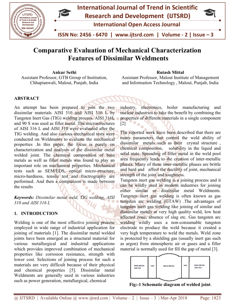
Fig:-1
1 Schematic diagram of welded joint.
joint
@ IJTSRD | Available Online @ www.ijtsrd.com | Volume – 2 | Issue – 3 | Mar-Apr
Apr 2018
Page: 1823
International Journal of Trend in Scientific Research and Development (IJTSRD) ISSN: 2456-6470
2456
2. Experimental:
In this research the dissimilar metal welding between
AISI 310 and AISI 316 L was carried out by using
TIG welding process with two different filler metals.
The base metal used for dissimilar welding were AISI
310 and AISI 316 L and thickness of base metals were
4 mm. AISI 316L and 90 S was used as filler metal.
The chemical compositions of base metal and filler
metals are shown in Tables 1 and 2, respectively
Table 1: Crhemical
hemical Composition of Base Metal
Fig: 2: Tensile Tested specimens
RESULT AND DISCUSSIONS:
For microstructure observations, the welded samples
were cut right angle to the welding direction from the
welded joints and after cutting the samples in small
pieces then polished and etched by using a kroll
solution. Optical micro-scope
scope was used to observe the
microstructure of the weld interface. Scanning
electron microscope (SEM) was used to observe the
microstructure, element distribution and fracture
analysis.
Table 2: Chemical Composition of Filler Metal
Metallurgical investigations of the joint were done
after polishing the weld samples. The samples were
prepared by first cutting in appropriate size by wire
cut machine and then grinding using 80,120, 400, 800,
600, 1000, 1500 and 2000 gritss of emery papers and
final polishing is done by using 0.5μm diamond
powder. Optical microstructure was measured along a
straight line starting from first base metal, HAZ, weld
metal, HAZ and ends at second base metal by an
optical-microscope
microscope and a scanni
scanning electron
microscope equipped with an energy dispersion X
XRay spectrometer (SEM/EDS). And micro hardness of
all three specimens is measure by micro
micro-vicker
hardness testing machine. The mechanical properties
of the welded joint were analyzed by conducting
various tests. The tensile test was performed at a
crosshead speed of 3 mm/min. The shape of the
specimens which were used for performing tensile
tests was dumbled shape and the length was 200mm
and width was 20mm as shown in fig: 2.
Fig 3. Optical micro-structure
structure of sample 1 AISI 310
and AISI 316L welded by filler Metal AISI 316 L
Fig 4. Optical micro-structure
structure of sample 2 AISI 310
and AISI 316 L welded by filler metal 90 S
MICROHARDNESS: Hardness measurements of
specimens were performed by means of Vickers
method along the straight
aight line starting from first base
metal, haz, wm, haz, and then second base metal.
Hardness results of all the samples are shown in table
3. In sample 1 the hardness values are lies in the range
of 145–160,
160, for sample 2 hardness values lies in the
range of 152-458.
@ IJTSRD | Available Online @ www.ijtsrd.com | Volume – 2 | Issue – 3 | Mar-Apr
Apr 2018
Page: 1824
International Journal of Trend in Scientific Research and Development (IJTSRD) ISSN: 2456-6470
2456
Figure 5. SEM of sample 1 and 2
Sample 1 AISI 310 AISI 316L AISI 316L.
Table: 5. EDS of sample 1
Table: 3. Shows comparison of micro
micro-hardness of
samples
TENSLIE TEST: A tensile test is the most common
type mechanical test we can perform to predict the
ultimate tensile strength of specimen. A tensile test is
fully standardized, simple and less expensive. By
pulling on something, you will very quickly determine
how the material will react to forces being applied in
tension. By pulling material, you will find its strength
along with how much it will elongate. One of the
properties you can determine about a material is its
ultimate tensile strength. This is the maximum lo
load
the specimen sustains during the test. The ultimate
tensile strength may or may not equate to the strength
at break. This all depends on what type of material
you are testing brittle, ductile or a substance that even
carries both properties. The test process
ocess involves
placing the test specimen in the machine and applying
tension to it until it fractures. [4]
Sample 2: AISI 310 90 s AISI 316L
Table: 6. EDS of sample 2
Tensile test of the samples were done on universal
testing machine and the ultimate tensile strength of
samples are shown in the fig: 6
Table: 4.Ultimate tensile strength of samples.
Ultimate tensile strength of all the samples is lies in
the range of 643-652.
SEM/EDS: Figure 5 shows an SEM (Scanning
electron micro-scope)
scope) images at the joint interface of
the sample 1 and 2 at magnification level of x33, x33
and x35 respectively. The composition of Cr, Fe and
Ni were observed in interface by EDS.
Fracture surface examination: Scanning electron
microscopy (SEM/EDS) photographs of fractured
surface of tensile tested samples normally show the
overall micro-cracks,
cracks, the striation, as well as beach
marks in the fractured region, and the dimples in the
ductile fracture region. SEM/EDS
SEM/ED photos of samples
are shown below in fig. 8.
Figure 6: figure a and b shows SAM sample 1 and 2
@ IJTSRD | Available Online @ www.ijtsrd.com | Volume – 2 | Issue – 3 | Mar-Apr
Apr 2018
Page: 1825
International Journal of Trend in Scientific Research and Development (IJTSRD) ISSN: 2456-6470
2456
EDS: Sample 1 310 316L 316L (310 left side fracture
piece)
1. The filler metal AISII 316L is better as
comparative to 90 S because the sample 1 which
contains AISI 316 L as a filler metal shows high
value of tensile strength in tensile test.
2. Hardness test reveals that improved values
compared to 90 S because of relatively high
values of micro hardness in HAZ and WM region
of sample containing 90 S as a filler metal.
3. Micro-structure
structure of HAZ and WM of sample 1
containing AISI 316 L as a filler metal shows that
inter metallic combination filler metal and weld
metal is sound.
4. Chemical Composition
osition of Filler Metal 316 L is
also better because it contain large amount of Cr,
Ni and Mo.
Thus it is concluded that filler metal AISI 316L is
better as comparative to filler metal 90 S.
REFFERENCES:
EDS: Sample 2 310 90 S 316L (316L Right side
fracture piece)
CONCLUSION:
Dissimilar material welding was done between AISI
316 L and AISI 310 with TIG welding using two
different filler material AISI 316 L and 90 S and
mechanical properties are evaluated by conducting
various tests and it is concluded that;
1. R. Nivas, P.K singh, G. Das, S.K Das, S. Kumar,
B. Mahato, K. Sivaparasada and M.Ghosh (2017),
“ A comparative study on micro-structre
micro
and
mechanical properties near interface for dissimilar
materials during conventional v-grooveand
v
narrow
gap welding.” Journal of manufacturing processes
vol. 25 pp.224-28.
2. Sajjad gholami shiri, Mohsen nazarzadeh,
Mahmood sharifitanar, Mehdi shafiee afarani
(2012), “ Gas tungsten arc welding of cpcp copper
to 304 ss using different filler meterials”, Trans.
Nonferrous met. Soc. China 22, pp 2937-2942.
2937
3. Prashant. K. S , Pnakaj. K, Baljeet. S, Rahul. K.S,
(2015), “ A review on TIG welding for optimizing
process parameters on dissimilar joints.”
International journal of engineering research and
applications, ISSN : 2248-9622
2248
vol. 5, issue 2,
pp.125-128.
4. Ravinder , S.K. Jarial, (2015),
(20
“Parametric
optimization of TIG welding on stainless steel
(202) and mild steel by using taguchi method”,
International journal of enhanced research in
science technology and engineering, vol.4 issue.6
pp:484-494.
5. Radha raman mishra, visnu kumar tiwari
tiwar and
rajesha, (2014), “ A study of tensile strength of
MIG and TIG welded dissimilar joints of mild
steel and stainless steel”, International journal of
advances in materials science and engineering
vol.3
@ IJTSRD | Available Online @ www.ijtsrd.com | Volume – 2 | Issue – 3 | Mar-Apr
Apr 2018
Page: 1826


