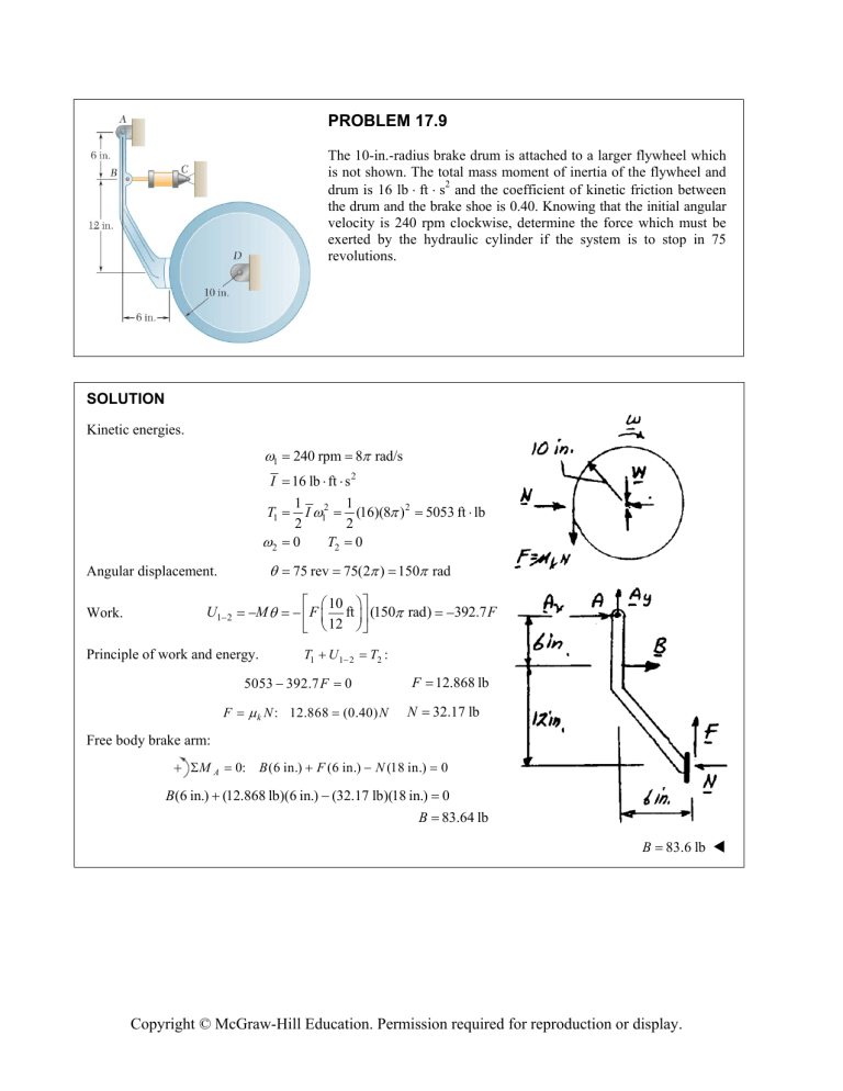
PROBLEM 17.9 The 10-in.-radius brake drum is attached to a larger flywheel which is not shown. The total mass moment of inertia of the flywheel and drum is 16 lb ft s2 and the coefficient of kinetic friction between the drum and the brake shoe is 0.40. Knowing that the initial angular velocity is 240 rpm clockwise, determine the force which must be exerted by the hydraulic cylinder if the system is to stop in 75 revolutions. SOLUTION Kinetic energies. 1 240 rpm 8 rad/s I 16 lb ft s 2 T1 2 Angular displacement. Work. U1 1 I 2 0 1 (16)(8 ) 2 2 T2 0 2 1 75 rev 2 M F Principle of work and energy. T1 k N: 75(2 ) 150 rad 10 ft 12 (150 rad) U1 T2 : 5053 392.7 F F 5053 ft lb 12.868 2 F 0 (0.40) N N 392.7 F 12.868 lb 32.17 lb Free body brake arm: MA 0: B (6 in.) F (6 in.) N (18 in.) 0 B(6 in.) (12.868 lb)(6 in.) (32.17 lb)(18 in.) 0 B 83.64 lb B 83.6 lb Copyright © McGraw-Hill Education. Permission required for reproduction or display. PROBLEM 17.11 Each of the gears A and B has a mass of 2.4 kg and a radius of gyration of 60 mm, while gear C has a mass of 12 kg and a radius of gyration of 150 mm. A couple M of constant magnitude 10 N m is applied to gear C. Determine (a) the number of revolutions of gear C required for its angular velocity to increase from 100 to 450 rpm, (b) the corresponding tangential force acting on gear A. SOLUTION Moments of inertia. mk 2 (2.4)(0.06)2 Gears A and B: IA IB Gear C: IC (12)(0.15)2 Kinematics. Kinetic energy. Position 1. rA A rB A B A B T 1 I 2 C A rC B 200 80 2.5 C 2 270 10 3 kg m2 C C 2.5 C : 100 rpm B 10 3 250 rpm rad/s 25 3 rad/s (T1 ) A 1 25 (8.64 10 3 ) 2 3 2 Gear A: (T1 ) B 1 25 (8.64 10 3 ) 2 3 2 Gear B: (T1 )C 1 10 (270 10 3 ) 2 3 2 Gear C: System: T1 Position 2. C A (T1 ) A 8.64 10 3 kg m2 (T1 ) B (T1 ) C 2.9609 J 2.9609 J 14.8044 J 20.726 J 450 rpm 15 rad/s B 37.5 rad/s Copyright © McGraw-Hill Education. Permission required for reproduction or display. PROBLEM 17.11 (Continued) 1 (8.64 10 3 )(37.5 )2 2 (T2 ) A Gear A: 59.957 J Gear B: (T2 ) B 1 (8.64 10 3 )(37.5 )2 2 Gear C: (T2 )C 1 (270 10 3 )(15 )2 2 299.789 J System: T2 (T2 ) A 419.7 J Work of couple. U1 2 M C (T2 ) B 10 59.957 J (T2 ) C C Principle of work and energy for system. T1 (a) U1 2 T2 : 20.726 10 C 419.7 C 39.898 radians Rotation of gear C. C Rotation of gear A. A 6.35 rev (2.5)(39.898) 99.744 radians Principle of work and energy for gear A. (T1 ) A MA A (T2 ) A : 2.9609 M A (99.744) MA (b) Tangential force on gear A. Ft 59.957 0.57142 N m MA rA 0.57142 0.08 Ft 7.14 N Copyright © McGraw-Hill Education. Permission required for reproduction or display. PROBLEM 17.14 The double pulley shown has a mass of 15 kg and a centroidal radius of gyration of 160 mm. Cylinder A and block B are attached to cords that are wrapped on the pulleys as shown. The coefficient of kinetic friction between block B and the surface is 0.2. Knowing that the system is at rest in the position shown when a constant force P 200 N is applied to cylinder A, determine (a) the velocity of cylinder A as it strikes the ground, (b) the total distance that block B moves before coming to rest. SOLUTION Kinematics. Let rA be the radius of the outer pulley and rB that of the inner pulley. vA rA C vB rB sA rA C sB rB sA rA C rB vA rA Use the principle of work and energy with position 1 being the initial rest position and position 2 being when cylinder A strikes the ground. T1 U1 2 T2 : where T1 0 and T2 1 mA v A2 2 with mA 5 kg, mB T2 mC kC2 15 kg, IC 1 mA 2 1 5 kg 2 mB rB2 IC rA2 rA2 1 mB vB2 2 (15 kg)(0.160 m)2 1 IC 2 2 C 0.384 kg m2 v A2 (15 kg)(0.150 m) 2 (0.250 m) 2 0.384 kg m 2 2 vA (0.250 m)2 (8.272 kg)v A2 Principle of work and energy applied to the system consisting of blocks A and B and the double pulley C. Work. where U1 2 sA Ps A mA g sA FF s B m B g s B sin 30 1m Copyright © McGraw-Hill Education. Permission required for reproduction or display. PROBLEM 17.14 (Continued) and rB sA rA sB 0.150 m (1 m) 0.250 m 0.6 m To find Ff use the free body diagram of block B. 60° F 0: NB m B g cos 30 0 NB m B g cos 30 (15 kg)(9.81 m/s) cos 30 Ff U1 k NB (0.2)(127.44 N) 127.44 N 25.487 N (200 N)(1 m) (5 kg)(9.81 m/s 2 )(1 m) 2 (25.487 N)(0.6 m) (15 kg)(9.81 m/s 2 )(0.6 m)sin 30 189.613 J Work-energy: (a) 0 189.613 J Velocity of A. vA (8.272 kg)vA2 4.7877 m/s vA 4.79 m/s when the cylinder strikes the ground, vB C rB vA rA vA rA 0.150 m (4.7877 m/s) 0.250 m 4.7877 m/s 0.250 m 2.8726 m/s 19.1508 rad/s After the cylinder strikes the ground use the principle of work and energy applied to a system consisting of block B and double pulley C. Let T3 be its kinetic energy when A strikes the ground. T3 1 1 mB vB2 I C C2 2 2 1 (15 kg)(2.8726 m/s) 2 2 132.305 J When the system comes to rest, U3 4 T4 1 (0.384 kg m 2 )(19.1508 rad/s)2 2 0 (25.487 N) sB (15 kg)(9.81 m/s 2 )( sB sin 30 ) (99.062 N) sB where s B is the additional travel of block B. T3 U3 4 T4 : 132.305 J (99.062 N) s B sB (b) Total distance: 0 1.3356 m sB sB 1.936 m Copyright © McGraw-Hill Education. Permission required for reproduction or display. PROBLEM 17.18 A slender 9 lb rod can rotate in a vertical plane about a pivot at B. A spring of constant k 30 lb/ft and of unstretched length 6 in. is attached to the rod as shown. Knowing that the rod is released from rest in the position shown, determine its angular velocity after it has rotated through 90°. SOLUTION Position 1: Unstretched Length Spring: Gravity: Kinetic energy: x1 CD ( 6 in. ) 14.866 6 8.8661 in. 0.73884 ft Ve 1 2 kx1 2 Vg Wh V1 Ve T1 0 x2 9 in. 6 in. 3 in. 0.25 ft Ve 1 2 kx2 2 1 (30 lb/ft)(0.73884) 2 2 8.1882 lb ft 7 ft 5.25 lb ft 12 8.1882 lb ft 5.25 lb ft 13.438 lb ft (9 lb) Vg Position 2: Spring: 1 (30 lb/ft)(0.25 ft) 2 2 0.9375 lb ft Copyright © McGraw-Hill Education. Permission required for reproduction or display. PROBLEM 17.18 (Continued) Gravity: Vg Wh 0 V2 Ve Vg 0.9375 lb ft Kinetic energy: v2 I T2 r 2 7 ft 12 1 1 9 lb mL2 (2 ft) 2 12 12 32.2 1 1 2 mv22 I 2 2 2 1 9 lb 2 32.2 T2 2 0.094138 7 ft 12 2 2 0.093168 slug ft 2 1 (0.093168) 2 2 2 2 2 Conservation of energy: T1 V1 T2 V2 0 13.438 0.094138 2 2 2 2 132.79 2 11.524 rad/s 0.9375 2 11.52 rad/s Copyright © McGraw-Hill Education. Permission required for reproduction or display.


