IRJET- A New Three Phase AC-DC-AC Five Level Multilevel Inverter

International Research Journal of Engineering and Technology (IRJET) e-ISSN: 2395-0056
Volume: 06 Issue: 04 | Apr 2019
www.irjet.net p-ISSN: 2395-0072
A NEW THREE PHASE AC-DC-AC FIVE LEVEL MULTILEVEL INVERTER
Abhishek Kumar
1
, Mr. Kaushal Sen
2
1
Research Scholar, Department of Electrical and Electronics Engineering, Oriental College of Technology, Bhopal
(M.P.) India
2
Assistant Professor, Department of Electrical and Electronics Engineering, Oriental College of Technology,
Bhopal (M.P.) India
-------------------------------------------------------------------------***------------------------------------------------------------------------
Abstract
: Now a days multilevel inverters are a very attractive solution for medium-voltage high-power conversion applications; they convert DC power to AC power at required output voltage and frequency level. In the design of multilevel inverters, different topologies have been evolved. These topologies include diode clamped multilevel 1 inverter, flying capacitor multilevel inverter and cascaded H bridge multilevel inverter. The main limitations of the conventional topologies are large
II. CONTROL AND MODULATION
TECHNIQUES OF MULTILEVEL INVERTERS
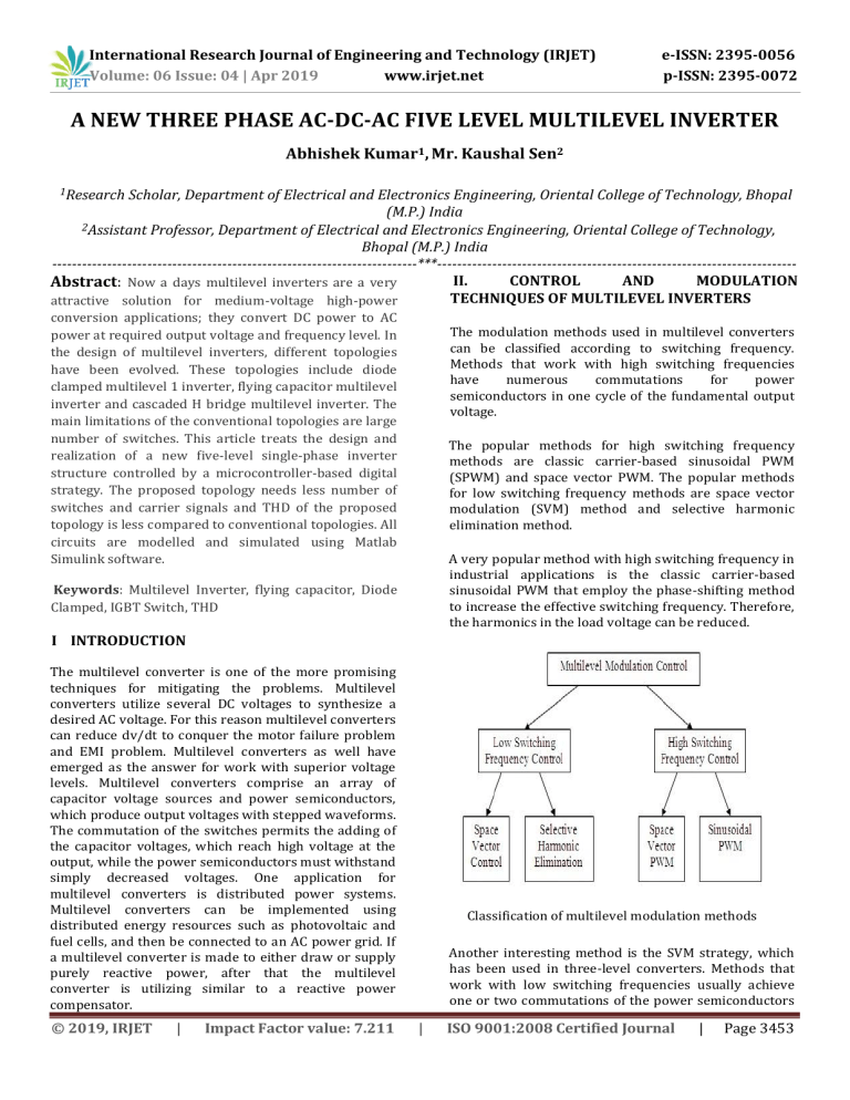
The modulation methods used in multilevel converters can be classified according to switching frequency.
Methods that work with high switching frequencies have numerous commutations for power semiconductors in one cycle of the fundamental output voltage. number of switches. This article treats the design and realization of a new five-level single-phase inverter structure controlled by a microcontroller-based digital strategy. The proposed topology needs less number of switches and carrier signals and THD of the proposed topology is less compared to conventional topologies. All circuits are modelled and simulated using Matlab
Simulink software.
Keywords : Multilevel Inverter, flying capacitor, Diode
Clamped, IGBT Switch, THD
I INTRODUCTION
The popular methods for high switching frequency methods are classic carrier-based sinusoidal PWM
(SPWM) and space vector PWM. The popular methods for low switching frequency methods are space vector modulation (SVM) method and selective harmonic elimination method.
A very popular method with high switching frequency in industrial applications is the classic carrier-based sinusoidal PWM that employ the phase-shifting method to increase the effective switching frequency. Therefore, the harmonics in the load voltage can be reduced.
The multilevel converter is one of the more promising techniques for mitigating the problems. Multilevel converters utilize several DC voltages to synthesize a desired AC voltage. For this reason multilevel converters can reduce dv/dt to conquer the motor failure problem and EMI problem. Multilevel converters as well have emerged as the answer for work with superior voltage levels. Multilevel converters comprise an array of capacitor voltage sources and power semiconductors, which produce output voltages with stepped waveforms.
The commutation of the switches permits the adding of the capacitor voltages, which reach high voltage at the output, while the power semiconductors must withstand simply decreased voltages. One application for multilevel converters is distributed power systems.
Multilevel converters can be implemented using distributed energy resources such as photovoltaic and fuel cells, and then be connected to an AC power grid. If a multilevel converter is made to either draw or supply purely reactive power, after that the multilevel converter is utilizing similar to a reactive power compensator.
Classification of multilevel modulation methods
Another interesting method is the SVM strategy, which has been used in three-level converters. Methods that work with low switching frequencies usually achieve one or two commutations of the power semiconductors
© 2019, IRJET | Impact Factor value: 7.211 | ISO 9001:2008 Certified Journal | Page 3453
International Research Journal of Engineering and Technology (IRJET) e-ISSN: 2395-0056
Volume: 06 Issue: 04 | Apr 2019
www.irjet.net p-ISSN: 2395-0072
during one cycle of the output voltages to generate a staircase waveform. Representatives of this family are the multilevel selective harmonic elimination based on elimination theory and the space-vector control (SVC).
III. GENERALIZED MULTILEVEL TOPOLOGY
Already available multilevel converters such as diodeclamped and capacitor-clamped multilevel converters is shown in Figure. Moreover, the generalized multilevel converter topology balance there voltage by there own , active or reactive power exchange, and without any assistance from other circuits at whichever number of levels automatically. Therefore, the topology gives a complete multilevel topology that embraces the offered multilevel converters in standard.
Fig shows the P2 multilevel converter structure per phase leg. Each diode, switching device, capacitor’s voltage is 1 V dc
, i.e., 1 /(m1 ) of the DC-link voltage. Any converter with any number of levels, with the traditional bi-level converter can be obtained using this generalized topology.
V o
2-level
V dc
Basic cell
V dc
3-level
V dc
V dc
4-level
V dc
V dc
V dc
5-level
V dc
V dc
V dc
V dc n-level
V dc
V dc
V dc
V dc
Generalized P2 multilevel converter topology
IV. BALANCE CONTROL PROBLEMS IN
MULTILEVEL INVERTERS
The diode-clamped multilevel converter could not have balanced voltages for real power conversion without sacrificing output voltage performance. Thus, diodeclamped multilevel converters are suggested to be applied to reactive and harmonic compensation to avoid the voltage balancing problem. The voltage unbalance problem could be solved by using a back-to-back rectifier/converter system and proper voltage balancing control. Other references suggested the use of additional voltage balancing circuits, such as DC choppers, etc.
The capacitor-clamped structure was originally proposed for high-voltage DC/DC conversions. It is easy to balance the voltages for such applications because the load current is DC. For the capacitor-clamped multilevel converter, voltage balancing is relatively complicated. It has been shown theoretically that the capacitor-clamped converter cannot have self-balanced voltage when applied to power conversion in which no real power is involved, such as reactive power compensation.
When the cascaded multilevel converter was introduced for motor drive applications, an isolated and separate DC source was needed for each H-bridge cell. However, another paper presented the idea of using cascade multilevel converter for reactive and harmonic compensation, from which isolated DC sources can be omitted. Additional work further demonstrated that the cascaded converter is suitable for universal power conditioning of power systems. The converter provides lower costs, higher performance, less EMI, and higher efficiency than the traditional PWM converter for power line conditioning applications, both series and parallel compensation. Although the cascaded converter has an inherent self-balancing characteristic, a slight voltage imbalance can occur because of the circuit component losses and limited controller resolution. A simple control method, which ensures DC voltage balance, has been proposed for reactive and harmonic compensation.
V SWITCHING CONTROL STRATEGY
For the equal DC voltage situation, the first-on, first-off strategy can be used to control the switching. The method can balance the switching loss during a whole cycle. This strategy also distributes the switchings between several DC levels, so each DC source can get an average switching time in a cycle, and balance the load between several DC levels.
For unequal DC voltage situation, the switchings for one
DC voltage level cannot be switched by the other DC voltage levels. Therefore, first-on, first-off strategy cannot be used to control the multilevel converters. As mentioned above, to eliminate a harmonic, a negative harmonic must be generated by the multilevel converter.
Because a specific voltage level is used to generate the negative harmonic, other voltage levels cannot be used to generate the harmonic because they have different voltage levels. One problem occurs if a voltage level cannot generate the negative harmonic based on its unipolar voltage waveform. To conquer the problem, the pulse-based switching control strategy is proposed here.
A harmonic voltage is split into a series of pulses. If a
© 2019, IRJET | Impact Factor value: 7.211 | ISO 9001:2008 Certified Journal | Page 3454
International Research Journal of Engineering and Technology (IRJET) e-ISSN: 2395-0056
Volume: 06 Issue: 04 | Apr 2019
www.irjet.net p-ISSN: 2395-0072
voltage level cannot generate the necessary pulse, another voltage level is used to generate this pulse.
VI. FOURIER SERIES AND HARMONICS
ELIMINATION THEORY
After apply Fourier theory to the output voltage the waveform of multilevel converters, which is odd quarterwave symmetric, we can find Fourier expression of the multilevel output voltage as. If the DC voltages are equal in the multilevel converter, the equation for fundamental frequency switching control method can be stated as:
V ( t )
n
1 , 3 , 5 ...
4 n
V
dc (cos( n
1
)
cos( n
2
)
cos( n
3
)
...
cos( n
s
)) sin( n
t )
(4.1)
From the equation, it can be observe that the output voltage has zero even harmonics because the output voltage waveform is odd quarter-wave symmetric. It also can be seen from that the peak values of these odd harmonics are expressed in terms of the switching angles
,
1
2
, … and
s
. Furthermore, the harmonic equations produced from (4.1) are transcendental equations.
Based on the harmonic removal theory, if one wants to eliminate the cos( n
1
)
n th harmonic, then cos( n
2
)
cos( n
3
)
...
cos( n
s
)
0
That means to choose a series of switching angles to let the value of the n th harmonic be zero. Therefore, an equation with s switching angles will be use to control the s different harmonic values. Generally, an equation with s switching angles is used to determine the fundamental frequency value, and to remove s -1 low order harmonics. For example, for an equation with three switching angles, (4.1) becomes
V ( t )
n
1 ,
3 , 5 ...
4 V dc n
(cos( n
1
)
cos( n
2
)
cos( n
3
)) sin( n
t )
(4.3)
Here, the fundamental peak value of the output voltage of V
1 should be controlled, and the 5 equations are: th and 7 th order harmonics should be eliminated. The resulting harmonic cos
1
cos
2
cos
3
V
1
4 V dc cos 5
1
cos
2
(4.4) cos
3
0 cos 7
1
cos
2
cos 7
(4.5)
3
0
(4.6)
To simplify the expression, (3.4) can be written as cos
1
cos
2
cos
3
m
Where
m
V
1
4 V dc
(4.7)
(4.8) is defined here as the modulation index. So
V
1 max
4
sV dc
(4.9)
Where s is the number of DC sources.
Here, the third harmonic has not been eliminated because the triplen harmonics can be robotically cancelled in the line-line voltages for balanced threephase systems. Therefore, the triplen harmonics are not selected for removal in the phase voltage.
These harmonic equations are transcendental equations.
They are complex to resolve without using some sort of numerical iterative technique, such as Newton’s technique. on the other hand, by making several simple changes of variables and simplifying, these transcendental equations can be transformed into a set of polynomial equations. Then, resulting theory can be employ to find all solutions to the harmonic equations.
VII. CONCLUSION
A new hybrid 5-level inverter topology and modulation technique is projected. Compared to 5-level ANPC as the most similar topology, this new topology requires 2 less switches at the value of a further capacitor and 6 diodes.
However, since the capacitors still see the switching frequency and their size remain a similar, it's expected to cut back the inverter’s total value. Also, in contrast to 5level ANPC, all switches must withstand a similar voltage which eliminates the requirement for series association of switches and associated coincident activate and off drawback. good loss distribution among switches can increase the inverters rated power or give higher switching frequency and smaller capacitance size.
VIII. REFERENCES
1) D. G. Holmes and T. A. Lipo, Pulse width modulation for power converters, IEEE press, 2003.
2) L. M. Tolbert, F. Z. Peng, T. G. Habetler, “Multilevel
Converters for Large Electric Drives,” IEEE Transactions on Industry Applications, vol. 35, no. 1, Jan./Feb. 1999, pp. 36-44.
3) P. N. Enjeti, P. D. Ziogas, J. F. Lindsay, “Programmed
PWM Techniques to eliminate Harmonics: A Critical
© 2019, IRJET | Impact Factor value: 7.211 | ISO 9001:2008 Certified Journal | Page 3455
International Research Journal of Engineering and Technology (IRJET) e-ISSN: 2395-0056
Volume: 06 Issue: 04 | Apr 2019
www.irjet.net p-ISSN: 2395-0072
Evaluation,” IEEE Transactions on Industry Applications, vol. 26, no. 2, March/April. 1990. pp. 302 – 316.
4)A. Nabae, I. Takahashi, and H. Akagi, “A new neutralpoint clamped PWM converter,” IEEE Transactions on
Industry Applications, vol. IA-17, pp. 518–523, Sept./Oct.
1981.
5) X. Yuan, H. Stemmler, and I. Barbi, “Investigation on the clamping voltage self-balancing of the three-level capacitor clamping converter,” in Proc. IEEE PESC’99,
1999, pp. 1059–1064.
6) C. Hochgraf, R. Lasseter, D. Divan, and T. A. Lipo,
“Comparison of multilevel converters for static var compensation,” in Conf. Rec. IEEE-IAS Annu. Meeting,
Oct. 1994, pp. 921–928.
7) P. Hammond, “A new approach to enhance power quality for medium voltage ac drives,” IEEE Transactions on Industry Applications, vol. 33, pp. 202–208, Jan./Feb.
1997.
8) E. Cengelci, S. U. Sulistijo, B. O. Woom, P. Enjeti, R.
Teodorescu, and F. Blaabjerge, “A new medium voltage
PWM converter topology for adjustable speed drives,” in
Conf. Rec. IEEE-IAS Annu. Meeting, St. Louis, MO, Oct.
1998, pp. 1416–1423.
9) F. Z. Peng, “A generalized multilevel converter topology with self voltage balancing,” IEEE Transactions on Industry Applications, vol. 37, pp. 611–618, Mar./Apr.
2001.
10) W. A. Hill and C. D. Harbourt, “Performance of medium voltage multilevel converters,” in Conf. Rec.
IEEEIAS Annu. Meeting, Pheonix, AZ, Oct. 1999, pp.
1186–1192.
11) M. D. Manjrekar, P. K. Steimer, and T. A. Lipo, “Hybrid multilevel power conversion system: a competitive solution for high-power applications,” IEEE Transactions on Industry Applications, vol. 36, pp. 834–841, May/June
2000.
12) J. S. Lai and F. Z. Peng, “Multilevel converters – A new breed of power converters,” IEEE Transactions on
Industry Applications, vol. 32, no. 3, May/June 1996, pp.
509-517.
13) J. Rodríguez, J. Lai, and F. Peng, “Multilevel converters: a survey of topologies, controls and applications,” IEEE Transaction on Industrial Electronics, vol. 49, no. 4, Aug. 2002, pp. 724-738.
© 2019, IRJET | Impact Factor value: 7.211 | ISO 9001:2008 Certified Journal | Page 3456


