IRJET-Train Impact Analysis on Prestressed Concrete Girder
advertisement
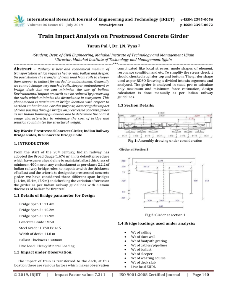
International Research Journal of Engineering and Technology (IRJET) e-ISSN: 2395-0056 Volume: 06 Issue: 07 | July 2019 p-ISSN: 2395-0072 www.irjet.net Train Impact Analysis on Prestressed Concrete Girder Tarun Pal 1, Dr. J.N. Vyas 2 1Student, Dept. of Civil Engineering, Mahakal Institute of Technology and Management Ujjain 2Director, Mahakal Institute of Technology and Management Ujjain -----------------------------------------------------------------------***-------------------------------------------------------------------- Abstract – Railway is best and economical medium of complicated like local stresses, mode shapes of element, resonance condition and etc. To simplify the stress check it should checked at girder top and bottom. The girder shape used as per RDSO Drawing is divided into six segments and analysed. The girder is analysed in staad pro to calculate only maximum and minimum force estimation, design calculation is done manually as per Indian railway guidelines. transportation which requires heavy rails, ballast and sleeper. On past studies the transfer of train load from rails to sleeper then sleeper to ballast forwarded to embankment. Generally we cannot change very much of rails, sleeper, embankment or bridge deck but we can minimize the use of ballast. Environmental impact on earth can be reduced by preserving the rocks which minimize the disturbance in ecosystem. This phenomenon is maximum at bridge location with respect to earthen embankment. For this purpose, observing the impact of train passing through bridge on prestressed concrete girder as per Indian Railway guidelines and to determine the ballast usage characteristics to minimize the cost of bridge and solution to minimize the structural weight. 1.3 Section Details: Key Words: Prestressed Concrete Girder, Indian Railway Bridge Rules, IRS Concrete Bridge Code Fig 1: Assembly drawing under consideration 1. INTRODUCTION From the start of the 20th century, Indian railway has adopted the Broad Gauge(1.676 m) in its default procedure which have general guideline to maintain ballast thickness of minimum 400mm on any embankment as per clause 2.2.2 of Indian railway bridge rules, to negotiate with the thickness of ballast and the criteria to design the prestressed concrete girder, we have considered three different span bridges (11.4m,15.4m,17.9m) and checking the variation of stress on the girder as per Indian railway guidelines with 300mm thickness of ballast for first trail. 1.1 Details of Bridge parameter for Design Bridge Span 1 : 11.4m Bridge Span 2 : 15.2m Fig 2: Girder at section 1 Bridge Span 3 : 17.9m Concrete Grade : M50 1.4 Bridge loadings used under analysis: Steel Grade : HYSD Fe 415 Width of deck : 11.8 m Ballast Thickness : 300mm Live Load : Heavy Mineral Loading 1.2 Impact under Observation: The impact of train is transferred to the deck, at this location there are various factors which makes observation © 2019, IRJET | Impact Factor value: 7.211 | Wt of railing Wt of duct wall Wt of footpath grating Wt of cables/pipelines Wt of ballast Wt of sleeper Wt of wearing course Wt of deck slab Live load EUDL ISO 9001:2008 Certified Journal | Page 140 International Research Journal of Engineering and Technology (IRJET) e-ISSN: 2395-0056 Volume: 06 Issue: 07 | July 2019 p-ISSN: 2395-0072 www.irjet.net Derailment Load Longitudinal forces & tractive force Stage 2 losses M3DL MFPLL + MLL 1.5 Abbreviation used: 375.813 452.708 666.388 921.764 733.715 211.157 M1DL = Moment due to self weight of girder M2DL = Moment due to diap. & deck slab M2’DL = Moment due to retainers M3DL = Moment due to remaining SIDL MFPLL = Moment due to Footpath live load MLL = Moment due to live load 2. Stress Results of Prestressed Concrete Girder calculated using Staad Pro & MS excel at section 1 As per chapter 11, IRS Concrete Bridge Code: - Chart 1: Stress at Girder Top comparison between span Table 1, For Span 11.4 m Loading Stage 1 + M1DL Stage 1 losses M2DL M2’DL Stage 2 prestress Stage 2 losses M3DL MFPLL + MLL Stress at Girder Top (t/m2) 69.568 83.113 258.61 266.201 415.636 409.932 468.126 680.438 Stress at Girder Bottom (t/m2) 486.798 424.014 239.232 215.713 1338.314 1112.793 932.498 274.725 Chart 2: Stress at Girder Bottom comparison between span Table 2, For Span 15.40m Loading Stage 1 + M1DL Stage 1 losses M2DL M2’DL Stage 2 prestress Stage 2 losses M3DL MFPLL + MLL Stress at Girder Top (t/m2) 91.838 123.971 366.756 374.328 537.410 543.104 654.900 980.174 3. CONCLUSIONS Stress at Girder Bottom (t/m2) 1045.349 896.402 640.772 617.309 1879.831 1542.706 1196.277 188.331 1. 2. 3. 4. Table 3, For Span 17.9 m Loading Stage 1 + M1DL Stage 1 losses M2DL M2’DL Stage 2 prestress Stress at Girder Top (t/m2) 127.186 138.748 251.892 261.587 377.030 © 2019, IRJET | ACKNOWLEDGEMENT Stress at Girder Bottom (t/m2) 314.944 264.291 147.225 123.515 1120.441 Impact Factor value: 7.211 As per Chart 1 & 2, the stress intensity of live load and footpath load is increasing in same manner at top, decreasing towards the bottom in traditional manner. The stress intensity of prestressing force is increased at bottom to compensate the tensile stresses. The changes in girder top stress are in linear variation and maintaining the variation in similar manner indicating the St. venant’s principle for local stress due to uniformly distributed load. The changes in girder bottom stress are similar for span 15.4m & 17.9m but low stress for span 11.4m indicating increase in impact of tensile at bottom. I would like to thank Director sir for their precious guidance and support. I would like to thank P.K. Sharma(AXEN/CON/SASR) and Rajesh Kumar (SSE/C/CWA) of S.E.C. Railway for their kind support. I also appreciate Ajay Kumar (XEN Design Bilaspur), S.E.C. Railway for providing data and kind support. | ISO 9001:2008 Certified Journal | Page 141 International Research Journal of Engineering and Technology (IRJET) e-ISSN: 2395-0056 Volume: 06 Issue: 07 | July 2019 p-ISSN: 2395-0072 www.irjet.net REFERENCES [1] [2] [3] [4] [5] [6] [7] Thakkar Kaushal Rajesh Kumar, “Response of steel railway bridges on 25T route due to train load”, Department of earthquake engineering, IIT Roorkee, June 2011 N. Krishna Raju, Prestressed Concrete Book, Tata McGraw Hill, 2018 IRS Concrete Bridge Code, 1997 Indian Railway Bridge Rules IS 456 2000, B.I.S. Concrete Technology, Indian railway Institute of civil engineering pune, March 2007 Indian Railway Permanent way manual, Indian railway Institute of civil engineering pune, second edition,2004 © 2019, IRJET | Impact Factor value: 7.211 | ISO 9001:2008 Certified Journal | Page 142
![R09 Milford_Haven_Bridge_collapse[1].doc](http://s2.studylib.net/store/data/015465362_1-bb07aa6fdf59abd6cc2325f232e56032-300x300.png)
