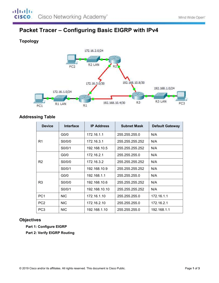
Packet Tracer – Configuring Basic EIGRP with IPv4 Topology Addressing Table Device Interface IP Address Subnet Mask Default Gateway G0/0 172.16.1.1 255.255.255.0 N/A S0/0/0 172.16.3.1 255.255.255.252 N/A S0/0/1 192.168.10.5 255.255.255.252 N/A G0/0 172.16.2.1 255.255.255.0 N/A S0/0/0 172.16.3.2 255.255.255.252 N/A S0/0/1 192.168.10.9 255.255.255.252 N/A G0/0 192.168.1.1 255.255.255.0 N/A S0/0/0 192.168.10.6 255.255.255.252 N/A S0/0/1 192.168.10.10 255.255.255.252 N/A PC1 NIC 172.16.1.10 255.255.255.0 172.16.1.1 PC2 NIC 172.16.2.10 255.255.255.0 172.16.2.1 PC3 NIC 192.168.1.10 255.255.255.0 192.168.1.1 R1 R2 R3 Objectives Part 1: Configure EIGRP Part 2: Verify EIGRP Routing © 2019 Cisco and/or its affiliates. All rights reserved. This document is Cisco Public. Page 1 of 3 Packet Tracer – Configuring Basic EIGRP with IPv4 Background In this activity, you will implement basic EIGRP configurations including network commands, passive interfaces and disabling automatic summarization. You will then verify your EIGRP configuration using a variety of show commands and testing end-to-end connectivity. Part 1: Configure EIGRP Step 1: Enable the EIGRP routing process. Enable the EIGRP routing process on each router using AS number 1. The configuration for R1 is shown. R1(config)# router eigrp 1 What is the range of numbers that can be used for AS numbers? 1 – 65,535 Step 2: Advertise directly connected networks. a. Use the show ip route command to display the directly connected networks on each router. How can you tell the difference between subnet addresses and interface addresses? Subnets are identified with a “C” and link addresses are identified with an “L”. b. On each router, configure EIGRP to advertise the specific directly connected subnets. The configuration for R1 is shown. R1(config-router)# network 172.16.1.0 0.0.0.255 R1(config-router)# network 172.16.3.0 0.0.0.3 R1(config-router)# network 192.168.10.4 0.0.0.3 Step 3: Configure passive interfaces. Configure the LAN interfaces to not advertise EIGRP updates. The configuration for R1 is shown. R1(config-router)# passive-interface g0/0 Step 4: Disable automatic summarization. The topology contains discontiguous networks. Therefore, disable automatic summarization on each router. The configuration for R1 is shown. R1(config-router)# no auto-summary Note: Prior to IOS 15 auto-summary had to be manually disabled. Step 5: Save the configurations. Part 2: Verify EIGRP Routing Step 1: Examine neighbor adjacencies. a. Which command displays the neighbors discovered by EIGRP? show ip eigrp neighbors b. All three routers should have two neighbors listed. The output for R1 should look similar to the following: IP-EIGRP neighbors for process 1 H Address Interface Hold Uptime (sec) © 2019 Cisco and/or its affiliates. All rights reserved. This document is Cisco Public. SRTT (ms) RTO Q Cnt Seq Num Page 2 of 3 Packet Tracer – Configuring Basic EIGRP with IPv4 0 1 172.16.3.2 192.168.10.6 Se0/0/0 Se0/0/1 14 12 00:25:05 00:13:29 40 40 1000 1000 0 0 28 31 Step 2: Display the EIGRP routing protocol parameters. a. What command displays the parameters and other information about the current state of any active IPv4 routing protocol processes configured on the router? show ip protocols b. On R2, enter the command you listed for 2a and answer the following questions: How many routers are sharing routing information with R2? 2 Where is this information located under? Routing Information Sources What is the maximum hop count? 100 Step 3: Verify end-to-end connectivity PC1, PC2 and PC3 should now be able to ping each other. If not, troubleshoot your EIGRP configurations. Suggested Scoring Rubric Activity Section Part 1: Configure EIGRP Question Location Possible Points Step 1 2 Step 2a 2 Part 1 Total Part 2: Verify EIGRP Routing 4 Step 1a 5 Step 2a 5 Step 2b 6 Part 2 Total 16 Packet Tracer Score 80 Total Score 100 © 2019 Cisco and/or its affiliates. All rights reserved. This document is Cisco Public. Earned Points Page 3 of 3
