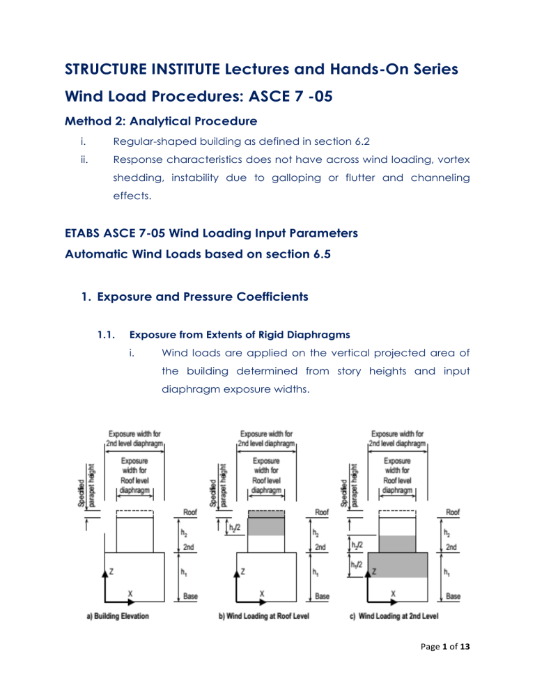
STRUCTURE INSTITUTE Lectures and Hands-On Series Wind Load Procedures: ASCE 7 -05 Method 2: Analytical Procedure i. Regular-shaped building as defined in section 6.2 ii. Response characteristics does not have across wind loading, vortex shedding, instability due to galloping or flutter and channeling effects. ETABS ASCE 7-05 Wind Loading Input Parameters Automatic Wind Loads based on section 6.5 1. Exposure and Pressure Coefficients 1.1. Exposure from Extents of Rigid Diaphragms i. Wind loads are applied on the vertical projected area of the building determined from story heights and input diaphragm exposure widths. Page 1 of 13 1.2. Exposure from Area Objects i. Wind loads are applied using the exposure from area objects method, are applied on the vertical and horizontal surfaces of the user selected area objects as described in section 6.5.12. 2. Wind Exposure Parameters 2.1. Wind Direction Angle i. Angle measured in degrees. ii. Angle is always measured counterclockwise from the positive global X-axis. iii. An angle “0” means, the wind is blowing to the positive global X-direction. iv. An angle “90” means, the wind is blowing to the positive global Y-direction. v. An angle “180” means, the wind is blowing to the negative global X-direction. vi. An angle “270” means, the wind is blowing to the negative global Y-direction. 2.2. Windward Coefficient, Cp i. Used in calculating pressure in the windward side. Page 2 of 13 2.3. Leeward Coefficient, Cp i. 2.4. Used in calculating pressure in the leeward side. Wind Cases (ASCE 7 05 figure 6-9) Page 3 of 13 2.5. Eccentricity Ratio e1 (from figure 6-9) 2.6. Eccentricity Ratio e2 (from figure 6-9) 3. Wind Coefficients 3.1. Wind Speed (mph) i. Is described in section 6.5.4 (refer to NSCP for local wind speed). A typical range of the basic wind speed is 85 to 150 mph. ii. Say 200 kph / 1.609 = 125 mph Page 4 of 13 3.2. Exposure Type i. Exposure A – deleted in ASCE 7-02 and later Extremely sheltered. Large city centers with tall buildings. ii. Exposure B Urban and suburban areas, wooded areas, areas with many closely spaced obstructions. Page 5 of 13 iii. Exposure C Open terrain with scattered obstructions. Airports, areas that are generally flat open country. iv. Exposure D Flat, unobstructed areas and water surfaces outside hurricane prone regions. Page 6 of 13 3.3. Wind Importance Factor, I i. Is described in table 6-1. A typical range of values for I is 0.77 to 1.15. 3.4. Topographical Factor, Kzt i. Is described in section 6.5.7.2. the default value for Kzt is 1.0 and cannot be < 1.0. ii. For flat terrain Kzt = 1.0 Page 7 of 13 Page 8 of 13 Page 9 of 13 3.5. Gust Effect Factor, G i. Is described in section 6.5.8. ii. G = 0.85 for stiff buildings and stiff structures. iii. For building f < 1 hertz, flexible buildings and other structures Calculate “G” by rational analysis that incorporates the dynamic properties of the main wind-force resisting system. Page 10 of 13 3.6. Directionality Factor, Kd i. Is described in section 6.5.4.4. a typical value for Kd is 0.85 to 0.95 Page 11 of 13 4. Exposure Height 4.1. Top Story i. 4.2. Highest story level to be assumed expose to wind loading. Bottom Story i. Lowest story level that is exposed to wind loading. It may be advantageous to specify a higher level as the bottom story for the wind loading. One example, if the building has several below grade levels that should not receive any wind loading. 5. ASCE 7 -05 Wind Load Cases Page 12 of 13 Page 13 of 13

