OP4510 User Manual
advertisement
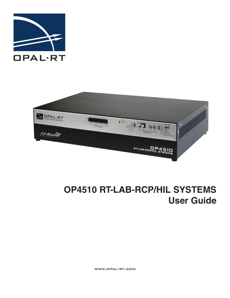
OP4510 RT-LAB-RCP/HIL SYSTEMS User Guide www.opal-rt.com Published by OPAL-RT Technologies, Inc. 1751 Richardson, suite 2525 Montreal, Quebec, Canada H3K 1G6 www.opal-rt.com © 2015 OPAL-RT Technologies, Inc. All rights reserved Printed in Canada SYMBOL DEFINITIONS The following table lists the symbols used in this document to denote certain conditions: Symbol Definition ATTENTION: Identifies information that requires special consideration TIP: Identifies advice or hints for the user, often in terms of performing a task REFERENCE _ INTERNAL: Identifies an additional source of information within the bookset. CAUTION Indicates a situation which, if not avoided, may result in equipment or work (data) on the system being damaged or lost, or may result in the inability to properly operate the process. Indicates a situation where users must observe precautions for handling electrostatic sensitive devices. ! CAUTION: Indicates a potentially hazardous situation which, if not avoided, may result in minor or moderate injury. It may also be used to alert against unsafe practices. ! WARNING: Indicates a potentially hazardous situation which, if not avoided, could result in serious injury or death. OP4510 User Guide OPAL-RT Technologies iii CONTENTS INTRODUCTION....................................................................................................................................... 7 RECEIVING AND VERIFICATION......................................................................................................... 8 Standard Hardware.............................................................................................................................................8 SIMULATOR ARCHITECTURE............................................................................................................. 9 USER INTERFACE.............................................................................................................................. 10 Front................................................................................................................................................................10 OP4510-1 Rear (standard configuration)..........................................................................................................11 OP4510-2 Rear (optional fiber optic configuration)..........................................................................................11 CONNECTING CABLES......................................................................................................................... 12 Testing I/O Signals. ..........................................................................................................................................12 DIN and DOUT Loopback Test....................................................................................................................................... 12 AIN and AOUT Loopback Test....................................................................................................................................... 12 GENERAL PIN ASSIGNMENTS ............................................................................................................ 13 SPECIFICATIONS................................................................................................................................... 14 I/O SPECIFICATIONS.......................................................................................................................... 15 32 Digital In (OP5353)......................................................................................................................................15 32 Digital Out (OP5360-2)................................................................................................................................15 16 Analog In (OP5340).....................................................................................................................................16 16 Analog Out (OP5330)..................................................................................................................................16 RS422 Digital In . .............................................................................................................................................16 RS422 Digital Out ...........................................................................................................................................16 LIMITED WARRANTY............................................................................................................................. 19 Limited Warranty...............................................................................................................................................19 Return Policy...................................................................................................................................................19 Exclusions. .......................................................................................................................................................19 Warranty Limitation and Exclusion....................................................................................................................20 Disclaimer of Unstated Warranties . .................................................................................................................20 Limitation of Liability .........................................................................................................................................20 OP4510 User Guide OPAL-RT Technologies 5 6 OPAL-RT Technologies OP4510 User Guide Introduction INTRODUCTION The OP4510 is a compact device with 128 fast I/O channels with signal conditioning, additional RS422 channels (or optional low-speed fiber optic channels), high-speed communication ports (SFPs), and is fully integrated with Simulink, SimPowerSystem. The integration of high-end INTEL multi-core processors with powerful Kintex 7 FPGA provides greater simulation power and sub-microsecond simulation time steps to maximize accuracy of fast power electronic systems. The OP4510 can simulate power grids with up to 200 nodes. WINDOWS HOST PC Ethernet OP4510 Solid State Disk Multicore CPU RAM LINUX OS SFP 4x 5 Gbits/s PCI-Express KINTEX 7 FPGA Carrier board DO DI D/A A/D DO DI RS422 RS422 16ch 16ch 32ch 32ch 6ch 6ch RS232 USB Figure 1: OP4510 system architecture (standard configuration) A series of standardized I/O configurations are available with the OP4510, each targeting specific applications. The System Description document provides detailed, specific bitstream information for the application purchased by the customer. OP4510 User Guide OPAL-RT Technologies 7 Introduction Receiving and Verification RECEIVING AND VERIFICATION After opening the package, remove the equipment and components. Make sure that all the items described in “Standard Hardware” are actually in the box and are undamaged. Standard Hardware The OP4510 real-time simulator includes the following basic hardware: Item Description OP4510 simulator System Integration binder Part Number N/A RT-LAB software CD O/S CD (Redhat) Documentation CD Loopback board Loopback cable C-02B-CAT6 RJ45 cable (1x) CAT6 (500 MHz) UTP Network Cable - Blue 10FT C-10B-CAT6 Power cable 1.83 m (6’) power cord, black (10A 125V) CPC06 126-0361 113-0737 OPAL-RT strongly recommends the use of anti-static wrist straps whenever handling any electronic device provided by OPAL-RT. Damage resulting from electrostatic charges will not be convered by the manufacturers warranty. ! 8 Disconnect power before servicing OPAL-RT Technologies OP4510 User Guide Introduction Receiving and Verification SIMULATOR ARCHITECTURE The following image illustrates the simulator’s architecture for each option using assembly views of the simulation hardware components within the OP4510 chassis. The OP4510 is an entry-level simulator that contains an FPGA carrier, which can accept four standard OPAL-RT mezzanine boards, in addition to the RS422 signals. Standard RS422 (Optional fiber optic) Type B mezzanines Figure 2: OP4510 Components (back view) The OP4510 can contain any 4 type B mezzanine boards, according to user needs. the standard OP4510-1 contains 2 digital and 2 analog boards (see “I/O Specifications” for details). These mezzanine boards interface using a DB37 connector at the back of the chassis. Four pairs of DB37F connectors provide up to 32 channels (Channel 00 to 15 and 16 to 31) and DB9 (RS422) connectors each provide an additional six channels. The OP4510 offers two types of synchronization, either LVDS or fiber optic, making it easier to synchronize with any OPAL-RT device. OP4510 User Guide OPAL-RT Technologies 9 Introduction User Interface USER INTERFACE Front A B C D A. Small Form-factor pluggable (SFP) module connectors provide 4 high speed communication links between OPAL-RT FPGAs or between FPGA and user controllers. The SFP use Aurora communication protocol. Use of these ports requires a custom bitstream. B. JTAG connector (for OPAL-RT technicians’ use only). C. Synchronization connectors status, and user configurable LEDs: LED Label Description PROG/ CFG OK: CFG OK steady on green and PROG off indicates the FPGA is functioning normally. CFG OK off and PROG steady on yellow indicates the the FPGA has stopped and is no longer functioning. RX: Green when receiving synchronization TX : Green when transmitting synchronization USER 1: Green LED controlled (configured by user using Simulink blocks) USER 2: Green LED controlled (configured by user using Simulink blocks) PWR ON: Green indicate OP4510 power is functioning MASTER/SLAVE: . Green indicates MASTER mode, Yellow indicates SLAVE mode. Flashing green and yellow indicates a SAFE bitstream in the FPGA 10 CHASSIS INDEX: 8-pin DIP switch that allows users to set the device’s network chassis index. It can be set from 00 to FF (in HEX) for a maximum of 256 addresses. SYNCHRO Label Description TX/RX Fiber optic connector. Compatible with OP4500, OP5607, OP7000 and OP7020. Synchronizes time steps between systems and includes high speed FPGA pulses. TX/RX Stereo jack. Compatible with all OPAL-RT products. OPAL-RT Technologies OP4510 User Guide Introduction User Interface D. Target computer monitoring interface. Two push buttons and 6 LED indicators: Name Interface Power Pushbutton Reset Pushbutton Power LED Green On indicates that the unit is powered up. HDD LED Green On indicates that the hard disk drive is operating. NIC1 LED Green On indicates that network port 1 is in use. NIC2 LED Green On indicates that network port 2 is in use. Power Fail LED Red On indicates a power fault. Red On indicates either that unit has overheated or a fan fault. Overheat/Fan Fail Status Description Power on or shut down the Target computer Resets the target computer OP4510-1 Rear (standard configuration) A A B C A. DB37 connectors for digital or analog inputs and outputs. B. DB9 connector module for RS422 signals, typically used to transmit differential encoder inputs and outputs. C. Standard computer connectors (left to right): mouse and keyboard, USB ports, monitor, network ports*. *Note that only one network port (the leftmost connector)is required for network connection; use of other connectors is optional. OP4510-2 Rear (optional fiber optic configuration) A A. Fiber optic connector module, providing 6RX andC6 TX channels. Each RxTx pair use Avago AFBR-2624Z (RX) and AFBR-1624Z (TX) These channels can be used as digital I/Os or for low-speed communication protocols. The ORION protocol, developped by OPAL-RT, is compatible with these channels and available in custom bitstreams. OP4510 User Guide OPAL-RT Technologies 11 Connecting Cables User Interface CONNECTING CABLES These are the basic cabling instructions for your OP4510. Use the cables provided to connect your devices, as instructed. 1. Connect power cord to unit and to appropriate power source (outlet). 2. Connect DB37 cables from OP4510 to external devices (motor, controller, etc.). Before connecting cables, make sure that amplitude are compatible with OPAL-RT DB37 amplitudes (see Specifications). 3. Connect DB9 cables (for RS422 signals) from OP4510 to external devices. You are now ready to power up your OP4510. Make sure that all cables are properly connected before powering up. Testing I/O Signals Before using your OP4510, it is good practice to test signals using the loopback board provided with the integration kit and RT-LAB, which lets you read any feedback from outputs to inputs. DIN and DOUT Loopback Test 1. Connect the loopback board to a Dout DB37 connector and connect the cable to a Din DB37 connector. 2. Connect the loopback board’s Vuser to a power source 3. Observe the Dout feedback on the Din using the integration model provided. AIN and AOUT Loopback Test 1. Connect the loopback board to an Aout DB37 connector and connect the cable to a Ain DB37 connector. 2. Observe the Aout feedback on the Ain using the integration model provided. 12 OPAL-RT Technologies OP4510 User Guide general Pin Assignments User Interface GENERAL PIN ASSIGNMENTS The following tables provide the generic pin assignments for the OP4510’s DB37 and DB9 connectors. More detailed information, tailored to specific firmware, can be found in the Integration documents provided with your order. DB37 pin 1 2 3 4 5 6 7 7 9 10 11 12 13 14 15 16 17 18 19 Channel pin assignment + 00 + 01 + 02 + 03 + 04 + 05 + 06 + 07 + 08 + 09 + 10 + 11 + 12 + 13 + 14 + 15 +12V* Vuser DB37 Channel pin assignment 20 - 00 21 - 01 22 - 02 23 - 03 24 - 04 25 - 05 26 - 06 27 - 07 28 - 08 29 - 09 30 - 10 31 - 11 32 - 12 33 - 13 34 - 14 35 - 15 36 DGND 37 Vrtn 1 20 - 00 - 01 - 02 - 03 - 04 - 05 - 06 - 07 - 08 - 09 - 10 - 11 - 12 - 13 - 14 - 15 00+ 01+ 02+ 03+ 04+ 05+ 06+ 07+ 08+ 09+ 10+ 11+ 12+ 13+ 14+ 15+ 12V Vuser DGND Vrtn 19 37 * Non-isolated, limited to 400mA DB9F Pin RS422 OUT CH 00-02 DB9F Pin RS422 IN CH00-02 1 TX0+ 1 RX0+ 2 TX1+ 2 RX1+ 3 TX2+ 3 RX2+ 4 N.C 4 N.C 5 +12V limited * 5 +12V limited * 6 TX0- 6 RX0- 7 TX1- 7 RX1- 8 TX2- 8 RX2- 9 DGND 9 DGND DB9F Pin RS422 OUT CH 03-05 DB9F Pin RS422 IN CH03-05 1 TX3+ 1 RX3+ 2 TX4+ 2 RX4+ 3 TX5+ 3 RX5+ 4 N.C 4 N.C 5 +12V limited * 5 +12V limited * 6 TX3- 6 RX3- 7 TX4- 7 RX4- 8 TX5- 8 RX5- 9 DGND 9 DGND DOUT RS422 DIN RS422 CH 00-02 CH 00-02 CH 03-05 CH 03-05 *Same 12V for all the connectors. 400mA total OP4510 User Guide OPAL-RT Technologies 13 Specifications User Interface SPECIFICATIONS Product name OP4510 RT-LAB-RCP/HIL SYSTEM OP4510-1, Standard RS422 OP4510-2, optional fiber optic FPGA Kintex-7 FPGA, 325T, 326,000 logic cells, 840 DSP slice (Multiplier- adder) Computer 8GB RAM. Xeon E3 4 core CPU, 3.2 GHz, solid state hard disk 128 GB I/O connectors OP4510-1 (standard) DB37F DB9 (RS422, 25 MHz) I/O module mezzanines 4 High speed communication port 4 SFP, 1 to 5 Gbits/s optical cable pairs (Rx/Tx) PC interface Standard PC connectors (monitor, keyboard, mouse and network) Power supply voltage range 90-132 or 185-260V, (115/230 auto) Frequency 50/60 Hz Dimensions (WxDxH) 43.2 x 27.4 x 8.9cm (17” x 10.8” x 3.5”) Weight Approx. 5 Kg (11 lbs) Operating temperature 10 to 40 ºC (50 to 104ºF) Storage temperature -55 to 85ºC (-67 to 185ºF) Relative humidity 10 to 90% non-condensing Maximum altitude 2000 m (6562 ft.) 14 OPAL-RT Technologies OP4510-2 (optional) DB37 Avago fiber optic (50 MBaud) OP4510 User Guide Specifications I/O Specifications I/O SPECIFICATIONS The OP4510 can hold any combination of four of the following Type B mezzanines. The standard OP4510-1 contains one of each. 32 Digital In (OP5353) Number of channels 32 digital inputs Isolation Optical isolator Connection mode Anode and cathode available on connector Input current 3.6 mA, current limiting diode Reverse voltage protection Schottky diode Maximum reverse voltage protection 30 Volts Detection threshold Separate Schmitt Trigger Voltage range 4 to 50 Vdc 32 Digital Out (OP5360-2) Number of channels 32 digital outputs 2 banks of 16, fully isolated and independant of each other Isolation Galvanic isolator Output Protection 50 mA resettable fuse Protection thresholds Over voltage: 30.1V Reverse voltage: maximum 30 V. Output Voltage range 5 to 30 Vdc max Output configuration Push-pull, tri-state output OP4510 User Guide OPAL-RT Technologies 15 Specifications I/O Specifications 16 Analog In (OP5340) Number of channels: 16 differential Resolution: 16 bits Input range (V) ±20v to ±120v 16 Analog Out (OP5330) Number of channels: 16 single-ended Resolution: 16 bits Default range: ± 16 Volts Maximum current: 15 mA RS422 Digital In Number of channels 6 differential inputs Isolation Optical isolator Detection threshold ± 0.2 V (for ± 7 V range) ± 0.5 V (for ± 15 V range) Input current ± 3 mA Voltage range 5 to 15 Vdc Delay Low-to-High 65 ns RS422 Digital Out Number of channels 6 differential outputs Isolation Galvanic isolator High level (With load) Low level (With load) 2.5 V min @ -20 mA 0.5 V max @ 20 mA Voltage range 5 to 15 Vdc Delay Low-to-High 55 ns 16 OPAL-RT Technologies OP4510 User Guide Specifications I/O Specifications OP4510 User Guide OPAL-RT Technologies 17 18 OPAL-RT Technologies OP4510 User Guide Limited Warranty LIMITED WARRANTY Limited Warranty OPAL-RT Technologies Inc. warrants to the original purchaser and/or ultimate customer (“Purchaser”) of OPAL-RT products (“Product”) that if any part thereof proves to be defective in material or workmanship within one (1) year, such defective part will be repaired or replaced, free of charge, at OPAL-RT Technologies’ discretion, if shipped prepaid to OPAL-RT Technologies Inc. at 1751 Richardson, suite 2525, Montreal, Quebec, Canada, H3K 3G6, in a package equal to or in the original container. The Product will be returned freight prepaid and repaired or replaced if it is determined by OPAL-RT Technologies Inc. that the part failed due to defective materials or workmanship. Otherwise, the fees will be charged to the client (see article “Warranty Limitation and Exclusion”). The repair or replacement of any such defective part shall be OPAL-RT Technologies’ sole and exclusive responsibility and liability under this limited warranty. Purchaser must request an RMA number before shipping any Product for repair: 1. Access the OPAL-RT website (www.opal-rt.com/support/ return-merchandise-authorization-rmarequest), click on support and select Return Merchandise (RMA). 2. Fill out the online form and submit. 3. OPAL-RT’s Support department will evalute the return and either issue an RMA number via email -- If the Product is returned for repair more than 12 months after purchase, the Purchaser is responsible for the cost of repair. OPAL-RT will assess the repair and prepare a quote. The RMA number will be sent with the quote. 4. Only when the Purchaser receives the RMA number, may they ship the Product, prepaid, to OPAL-RT. Return Policy the following fees will apply when customers return products for credit: A full credit, less a 15% fee and less return fee will only be issued if the product is in perfect working condition and if the product is returned within 1 month following the shipping date. If repairs are required on the returned product, the cost of these repairs will be deducted from the credit to be issued. No credits will be issued beyond the one month period. Exclusions If third party products are part of the Product, OPAL-RT will honor the original manufacturer’s warranty. This limited warranty does not cover consumable items, such as batteries, or items subject to wear or periodic replacement, including lamps, fuses or filter elements. OP4510 User Guide OPAL-RT Technologies 19 Limited Warranty Warranty Limitation and Exclusion OPAL-RT Technologies will have no further obligation under this limited warranty. All warranty obligations of OPAL-RT Technologies are void if the Product has been subject to abuse, misuse, negligence, or accident or if the Purchaser fails to perform any of the duties set forth in this limited warranty or if the Product has not been operated in accordance with instructions, or if the Product serial number has been removed or altered. Disclaimer of Unstated Warranties The warranty printed above is the only warranty applicable to this purchase. All other warranties, express or implied, including, but not limited to, the implied warranties of merchantability or fitness for a particular purpose are hereby disclaimed. Limitation of Liability It is understood and agreed that OPAL-RT Technologies’ liability, whether in contract, in tort, under any warranty, in negligence or otherwise shall not exceed the amount of the purchase price paid by the purchaser for the product and under no circumstances shall OPAL-RT Technologies be liable for special, indirect, or consequential damages. The price stated for the product is a consideration limiting OPAL-RT Technologies’ liability. No action, regardless of form, arising out of the transactions under this warranty may be brought by the purchaser more than one year after the cause of actions has occurred. 20 OPAL-RT Technologies OP4510 User Guide CONTACT OPAL-RT Corporate Headquarters 1751 Richardson, Suite 2525 Montréal, Québec, Canada H3K 1G6 Tel.: 514-935-2323 Toll free: 1-877-935-2323 Note: While every effort has been made to ensure accuracy in this publication, no responsibility can be accepted for errors or omissions. Data may change, as well as legislation, and you are strongly advised to obtain copies of the most recently issued regulations, standards, and guidelines. This publication is not intended to form the basis of a contract. Technical Services www.opal-rt.com/support UM15-18121_RVN 1.0 07/2015 © OPAL-RT Technologies Inc.
