User Manual MTi 1-series DK
Document MT0513P, Revision A, 8 Jul 2015
Features
Description
Easy to use Development Board
Full functionality
The MTi 1-series Development Kit is an excellent tool
to start working with the MTi 1-series. It has a premounted MTi-3-8A7G6 AHRS and comes with the
extensive MT Software Suite and USB-cabling. This
software suite is uniform and suitable for all Xsens’
products, including the high-performance MTi 100series. This makes the MT Software Suite full-featured,
with logging and visualization options, intuitive
configuration windows and possibilities to export data
for use in other programs. The Software Development
Kit contains source code for communication and
libraries for data processing.
Complete MT Software Suite
o MT Manager logging and visualization GUI
o SDK for Windows, Linux, embedded
o Magnetic Field Mapper
Delivered with MTi-3-8A7G6 mounted
API-compatible with all Xsens’ Motion Trackers
o Drivers and examples on ARM® mbedTM
USB, RS232, UART, SPI, I2C interfaces
Related Resources
www.xsens.com/MTi-1-series
MTi 1-series Data sheet (MT0512P)
MT Manager User Manual (MT0216P)
The 24-pins header connects to all interfaces available
on the MTi 1-series module. Connections with
development platforms for Cortex-M processors of
different brands can be made easy using the Xsens
examples on the mbed.org website.
MT Low Level Communication Protocol
Documentation
MT Low Level Communication Protocol
Documentation (MT0101P)
MTi White Paper: Next generation Xsens Motion
Trackers for Industrial applications
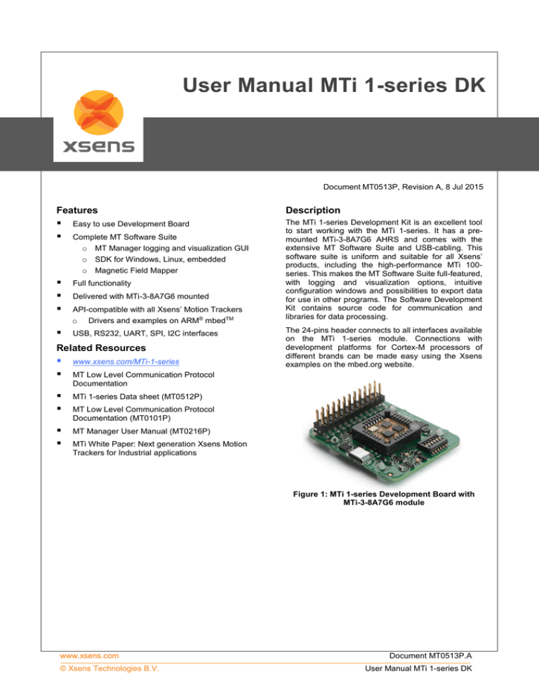
Figure 1: MTi 1-series Development Board with
MTi-3-8A7G6 module
www.xsens.com
© Xsens Technologies B.V.
Document MT0513P.A
User Manual MTi 1-series DK
Table of Contents
TABLE OF CONTENTS .................................................................................................................................................... 2
GENERAL INFORMATION .................................................................................................................................. 3
1
1.1
ORDERING INFORMATION .................................................................................................................................... 3
GETTING STARTED ............................................................................................................................................ 4
2
2.1.1
2.1.2
2.1.3
2.1.4
2.1.5
2.1.6
2.1.7
Installing MT Software Suite ................................................................................................................ 5
Connecting your device to MT Manager ................................................................................................ 6
Displaying data in MT Manager ........................................................................................................... 6
Configuring the MTi 1-series ................................................................................................................ 7
Other functionality of MT Manager ...................................................................................................... 7
Embedded examples ........................................................................................................................... 7
Frames of reference used in MTi 1-series ............................................................................................... 8
PACKAGE AND HANDLING ................................................................................................................................. 9
3
DEVELOPMENT KIT ............................................................................................................................................ 9
3.1.1
Connections and peripheral switch ..................................................................................................... 10
3.2 PIN DESCRIPTIONS ........................................................................................................................................... 11
3.2.1
Schematics ....................................................................................................................................... 12
3.2.2
Physical dimensions .......................................................................................................................... 14
3.2.3
Electrical specifications ..................................................................................................................... 14
3.3 ABSOLUTE MAXIMUM RATINGS ............................................................................................................................ 15
3.1
TRADEMARKS AND REVISIONS ........................................................................................................................ 16
4
4.1
4.2
TRADEMARKS ................................................................................................................................................ 16
REVISIONS .................................................................................................................................................... 16
www.xsens.com
© Xsens Technologies B.V.
2
Document MT0513P.A
User Manual MTi 1-series DK
1
General information
1.1
Ordering Information
Part Number
MTi-3-8A7G6-DK
Output
Package
Development kit for MTi 1-series,
including MTi-3-8A7G6
www.xsens.com
© Xsens Technologies B.V.
Packing Method
Single unit
3
Document MT0513P.A
User Manual MTi 1-series DK
2
Getting started
The MTi 1-series Development Kit contains
the Development Board with the MTi 1-series mounted;
a micro-USB to USB-B cable;
the MT Software Suite on a USB flash drive
The MTi Development Board has the following layout:
Figure 2: Top view of the MTi 1-series Development Board with the various components
Figure 3: Bottom view of the MTi 1-series Development Board with the description of the header and switch.
Text is displayed as see-through.
www.xsens.com
© Xsens Technologies B.V.
4
Document MT0513P.A
User Manual MTi 1-series DK
2.1.1
Installing MT Software Suite
The MT Software Suite is delivered on a USB flash drive in the Development Kit. The following will be installed:
The installation procedure consists of a set of several installers and starts with this screen:
It is possible to choose the components that you need to install.
When you cancel the installation of a particular component, the installer will continue with the next component. Make
sure to accept the End-User License agreement and Software License Agreements
Figure 4: Xsens MT Manager EULA
www.xsens.com
© Xsens Technologies B.V.
5
Document MT0513P.A
User Manual MTi 1-series DK
2.1.2
Connecting your device to MT Manager
Connect the Development Board to your PC using the supplied USB cable. With the USB cable, the Development
Board is automatically found.
Note: When you already have products from Xsens installed, there is a chance that the Development board will be
incorrectly identified as a serial mouse or serial ballpoint. Navigate to the Device Manager, double-click “Motion
Tracker Development Board Virtual COM” and click “Advanced” under “Port Settings”. Uncheck the box “Serial
Enumerator”.
Figure 5: Serial Enumerator must be unticked for the MTi 1-series Development Board to prevent
identification as a serial mouse or ballpoint
2.1.3
Displaying data in MT Manager
When the MTi Development Board is connected, click the 3D View icon:
representation of the MTi.
The other visualizations can be opened using the windows toolbar:
. This will result in a 3D box
.
Refer to the MT Manager User Manual for more information on these graphs and their features. The MT Manager
User Manual can be found via Help – Documentation.
www.xsens.com
© Xsens Technologies B.V.
6
Document MT0513P.A
User Manual MTi 1-series DK
2.1.4
Configuring the MTi 1-series
MT Manager is an excellent tool to configure the MTi 1-series. Click the Output Configuration button:
The following screen appears:
By default, the output of the MTi 1-series is orientation only. Click “Inertial Data” (∆q/∆v or Rate of Turn/Acceleration)
and “Magnetic Field” to be able to show this data in MT Manager.
2.1.5
Other functionality of MT Manager
With the MT Manager, it is possible to record data and export that data for use in other programs, configure
synchronization options and to review the test and calibration report.
More information on the functions in MT Manager can be found in the MT Manager User Manual.
2.1.6
Embedded examples
The MTi 1-series is designed for easy integration in embedded systems. To aid in development example code is
provided for the ARM mbed platform. An example implementation of the Xbus Low Level Communication Protocol is
provided as generic C99 compliant source code1, while an ARM mbed specific application demonstrates the use of
the Xbus library to communicate with an MTi 1-series development kit using UART communications.
The example code has been tested with the following ARM mbed compatible boards:
ST Nucleo F302R8 – Cortex M4
FreeScale FRDM-KL46Z – Cortex M0+
NXP EA LPC 4088 – Cortex M4
The example code is available at http://www.mbed.org/teams/Xsens. Documentation on how-to-use is provided on the
description page and in the code. Note that these examples are provided as is and are not supported by the Xsens
support team. The examples are licensed under the Apache Licence version 2.0.
Several basic commands were used, it is easy to extend the program with commands from the Xsens Low Level
Communication Protocol (LLCP). This protocol is documented in detail in the MT Software Suite and in the Low Level
Communication Protocol Documentation.
1
Xbus example code is not specific to ARM processors and should be compatible with other embedded architectures.
www.xsens.com
© Xsens Technologies B.V.
7
Document MT0513P.A
User Manual MTi 1-series DK
2.1.7
Frames of reference used in MTi 1-series
The MTi 1-series uses a right-handed coordinate system as the basis of the sensor of frame.
The following data is outputted in corresponding reference coordinate systems:
Data
Symbol
Reference
coordinate system
Acceleration
ax, ay, az
Sensor-fixed
Rate of turn
ωx, ωy, ωz
Sensor-fixed
Magnetic field
mx, my, mz
Sensor-fixed
Free acceleration
a
Local Tangent Plane
(LTP), default ENU
Velocity increment
∆vx, ∆vy, ∆vz
Local Tangent Plane
(LTP), default ENU
Orientation increment
∆q0, ∆q1, ∆q2, ∆q3
Local Tangent Plane
(LTP), default ENU
Orientation
Euler angles, quaternions or
rotation matrix (DCM)
Local Tangent Plane
(LTP), default ENU
Local Tangent Plane (LTP) is a local linearization of the Ellipsoidal Coordinates (Latitude, Longitude, Altitude) in the
WGS-84 Ellipsoid.
z
x
y
Figure 6: Default sensor fixed system for the MTi 1-series
Development Board with MTi.
It is straightforward to apply a rotation matrix to the MTi, so that the velocity and orientation increments, free
acceleration and the orientation output is using that coordinate frame. The default reference coordinate system is
East-North-Up (ENU) and the MTi 1-series has predefined outputs for North-East-Down (NED) and North-West-Up
(NWU). Any arbitrary alignment can be entered. These orientation resets have effect on all outputs that are by default
outputted with an ENU reference coordinate system.
www.xsens.com
© Xsens Technologies B.V.
8
Document MT0513P.A
User Manual MTi 1-series DK
3
Package and handling
Note that this is a mechanical shock (g) sensitive device. Proper handling is required to prevent damage to the part.
Note that this is an ESD-sensitive device. Proper handling is required to prevent damage to the part.
3.1
Development Kit
The MTi 1-series is available with a development kit. An MTi-3 AHRS is mounted in a PLCC-28 socket and connects
to USB, RS232, UART, I2C and SPI. The MTi-1 series DK comes with MT Manager, an intuitive GUI for Linux and
Windows, example code and example applications.
The Development Board exposes the pins of the MTi-1 on an easy to use 24-pins header allowing easy connectivity
during prototyping.
Figure 7: MTi 1-series Development Board
www.xsens.com
© Xsens Technologies B.V.
9
Document MT0513P.A
User Manual MTi 1-series DK
3.1.1
Connections and peripheral switch
The MTi Development Board has the following connections and switches:
Table 1.
24-pins dual row header with a pitch of 2.54 mm: The table below shows the connections: For information
on the connections, refer to the pin description in section 3.2. Refer to Table 3 how to enable the various
interfaces on the Development Board.
Connections on 24-pins header
Pin nr
Table 2.
1
VDD
2
VDDIO
3
GND
4
GND
5
nRST
6
NC
7
NC
8
NC
9
UART TX or I2C SCL
10
RS232-TX
11
UART RX or I2C SDA
12
RS232-RX
13
UART-RTS
14
RS232-RTS
15
UART-CTS or DRDY
16
RS232-CTS
17
SPI-SCK
18
GND
19
SPI-MISO
20
RESERVED
21
SPI-MOSI
22
SYNC_IN
23
SPI-nCS
24
GND
Micro USB: the MTi-1 Development Board has a micro USB connection that can be used to connect directly
to a USB port on a PC or laptop. To enable the communication via USB, make sure to have the peripheral
selection set to UART (full duplex).
Peripheral switch: This switch sets the interface configuration of the 12.1 x 12.1 mm module in the socket of
the MTi-1 Development Board.
Settings for switch
Lever nr
Description
Comments
VDDIO_3.0V
Sets the VDDIO of UART, SPI and I2C to 3.0V, if VDDIO is
not supplied to pin nr 2 of the 24-pins connector. Setting a
VDDIO, either external or with this lever, is required to
properly define the voltage levels of SYNC_IN.
2
VDDIO_1.8V
Sets the VDDIO of UART, SPI and I2C to 1.8V, if VDDIO is
not supplied to pin nr 2 of the 24-pins connector. When
VDDIO_3.0V is selected as well, VDDIO will be 3.0V. Setting
a VDDIO, either external or with this lever, is required to
properly define the voltage levels of SYNC_IN.
3
PSEL0
1
4
2
Pin nr
PSEL1
PSEL0
PSEL1
Peripheral2
0
0
UART_FD
1
0
UART_HD
0
1
SPI
1
1
I2C
5
RS232
Set this lever to 1 (high) to enable RS232 communication.
Also, PSEL0 and PSEL1 must be set to UART. This lever
must be set to 0 to enable I2C
6
NC
N/A
Note that the values for the peripheral selection on the switch are inverted with respect to the values on the module
www.xsens.com
© Xsens Technologies B.V.
10
Document MT0513P.A
User Manual MTi 1-series DK
Table 3.
Switch positions to enable interfaces on Development Board
Interface
PSEL0
PSEL1
RS232
Comments
UART FD
0
0
0
When USB is detected, interface is USB
UART HD
1
0
0
USB
0
0
0
I2C
1
1
0
SPI
0
1
0
RS232
0
0
1
3.2
When USB is detected, interface is USB
When USB is detected, interface is USB
Figure 8: Switch to
I2C interface and
VDDIO of 3.0V
Pin Descriptions
Name
Type
Description
Power Interface
VDD
Power
Power supply voltage for sensing elements
VDDIO
Power
Digital I/O supply voltage
Controls
PSEL0
PSEL1
These pins determine the signal interface. See table below. Note that when the
Selection pins PSEL0/PSEL1 is not connected, its value is 1. When PSEL0/PSEL1 is connected
to GND, its value is 0
nRST
Active low reset pin, connect to VDDIO if not used
Signal Interface
I2C_SDA
I2C_SCL
I2C interface
SPI_nCS
SPI_MOSI
SPI_MISO
I2C serial data
I2C serial clock
SPI chip select
SPI interface
SPI_SCK
SPI serial data input (slave)
SPI serial data output (slave)
SPI serial clock
RTS
Hardware flow control in UART full duplex mode (Ready-to-Send)
CTS
Hardware flow control in UART full duplex mode (Clear-to-Send)
nRE
DE
UART
interface
Receiver control signal in UART half duplex mode
Transmitter control signal in UART half duplex mode
UART-RX
Receiver data input
UART-TX
Transmitter data output
RS232-TX
Receiver data input
RS232-RX
RS232-RTS
RS232
interface
RS232-CTS
SYNC_IN
DRDY
Transmitter data output
Hardware flow control in RS232 mode (Ready-to-Send)
Hardware flow control in RS232 mode (Clear-to-Send)
SYNC_IN accepts a trigger which has the following functionality, depending on the
configuration set in the firmware
Sync interface
It sends out the latest available data message, or
It adjusts the bias of the clock onboard the MTi
Data ready
www.xsens.com
© Xsens Technologies B.V.
Data ready pin indicates that data is available (SPI / I2C)
11
Document MT0513P.A
User Manual MTi 1-series DK
3.2.1
Schematics
USB
Peripheral selection
24 pins header
www.xsens.com
© Xsens Technologies B.V.
12
Document MT0513P.A
User Manual MTi 1-series DK
RS232
Power
Level Translators
www.xsens.com
© Xsens Technologies B.V.
13
Document MT0513P.A
User Manual MTi 1-series DK
Figure 9: Physical location of components
3.2.2
Physical dimensions
Figure 10: The outer dimensions of the MTi DEV Board. PCB spacers are placed
3.2.3
Electrical specifications
The Development Board has the same communication protocol as the MTi 1-series module. The table below shows
the electrical specifications for the Development Board.
Table 4.
System specifications Development Board
Min
Typ
Max
Unit
VDD
3.3
5.5
V
VDDIO
1.6
5.5
V
SyncIn
VIH
VIL
www.xsens.com
© Xsens Technologies B.V.
0.75 * VDDIO
Comments
V
0.25 * VDDIO
14
V
Document MT0513P.A
User Manual MTi 1-series DK
3.3
Absolute maximum ratings
Min
Max
Unit
Storage temperature
-40
+125
ºC
Operating temperature
-30
+85
ºC
VDD
0.3
6.0
V
VDDIO
0.3
VDD + 0.5
V
7.0
V
10,000
g
Any axis, unpowered, for 0.2 ms
±2000
V
Human body model
VSYNC_IN
Acceleration
ESD
3
4
3
protection4
Comments
This is a mechanical shock (g) sensitive device. Proper handling is required to prevent damage to the part.
This is an ESD-sensitive device. Proper handling is required to prevent damage to the part.
www.xsens.com
© Xsens Technologies B.V.
15
Document MT0513P.A
User Manual MTi 1-series DK
4
Trademarks and revisions
4.1
Trademarks
© 2005-2015, Xsens Technologies B.V. All rights reserved. Information in this document is subject to change without
notice. Xsens, MVN, MotionGrid, MTi, MTi-G, MTx, MTw, Awinda and KiC are registered trademarks or trademarks of
Xsens Technologies B.V. and/or its parent, subsidiaries and/or affiliates in The Netherlands, the USA and/or other
countries. All other trademarks are the property of their respective owners.
4.2
Revisions
Revision
Date
By
Changes
A
8 July 2015
MHA
Initial release
www.xsens.com
© Xsens Technologies B.V.
16
Document MT0513P.A
User Manual MTi 1-series DK


