Before Use
Names of Parts of Product and Handling Precautions
Pressure Sensor
PSE57
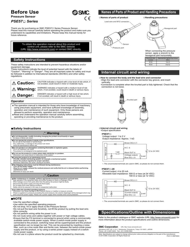
Names of parts of product
Series
Handling precautions
Lead wire and M12 coneector
Thank you for purchasing an SMC PSE57 Series Pressure Sensor.
Please read this manual carefully before operating the product and make sure you
understand its capabilities and limitations. Please keep this manual handy for
future reference.
Hexagonal part
To obtain the operation manual about this product and
control unit, please refer to the SMC website
(URL http://www.smcworld.com) or contact SMC directly.
Sensor
Pressure port
When connecting the pressure
sensor, apply a wrench to the
hexagonal part horizontally.
Nominal size
screws
Safety Instructions
These safety instructions are intended to prevent hazardous situations and/or
equipment damage.
These instructions indicate the level of potential hazard with the labels of
"Caution", "Warning" or "Danger". They are all important notes for safety and must
be followed in addition to International standards (ISO/IEC) and other safety
regulations.
Caution:
CAUTION indicates a hazard with a low level of risk which, if
not avoided, could result in minor or moderate injury.
Warning:
WARNING indicates a hazard with a medium level of risk
which, if not avoided, could result in death or serious injury.
Danger:
DANGER indicates a hazard with a high level of risk which,
if not avoided, will result in death or serious injury.
Appropriate tightening torque
(Nm)
R1/8
3 to 5
R1/4
8 to12
Internal circuit and wiring
How to connect the body and the lead wire and connector
•Align the lead wire connector with the connector key groove, and insert
vertically.
•Connection is complete when the knurled part is fully tightened. Check that the
connection is not loose.
Knurled part
Operator
The operation manual is intended for those who have knowledge of machinery
using pneumatic equipment, and have sufficient knowledge of assembly,
operation and maintenance of such equipment. Only those persons are
allowed to perform assembly, operation and maintenance.
Read and understand the operation manual carefully before assembling,
operating or providing maintenance to the product.
Do not operate the product outside of the specifications.
Do not use for flammable or harmful fluids.
Fire, malfunction, or damage to the product can result.
Verify the specifications before use.
Do not operate in an atmosphere containing flammable or explosive gases.
Fire or an explosion can result.
This product is not designed to be explosion proof.
Do not use the product in a place where static electricity is a problem.
Otherwise it can cause failure or malfunction of the system.
If using the product in an interlocking circuit:
•Provide a double interlocking system, for example a mechanical system
•Check the product regularly for proper operation
Otherwise malfunction can result, causing an accident.
The following instructions must be followed during maintenance:
•Turn off the power supply
•Stop the air supply, exhaust the residual pressure and verify that the air is released before performing
maintenance work
Otherwise an injury can result.
Caution
After maintenance is complete, perform appropriate functional inspections and leak tests.
Stop operation if the equipment does not function properly or there is a leakage of fluid.
When leakage occurs from parts other than the piping, the product might be faulty.
Disconnect the power supply and stop the fluid supply.
Do not apply fluid under leaking conditions.
Safety cannot be assured in the case of unexpected malfunction.
Use within the specified operating pressure.
Otherwise it can cause damage to the Pressure Sensor or inability to measure correctly.
If fluid is supplied at a pressure exceeding the proof pressure, the ceramic diaphragm will be damaged which may
short circuit the power supply. Please use a power supply which includes short circuit protection.
•PSE57
Voltage output: 1 to 5 V
Output impedance: Approx. 1 kΩ
Brown DC(+)
Main circuit
Warning
Do not disassemble, modify (including changing the printed circuit board) or repair.
An injury or failure can result.
Internal circuit and wiring
•Output specification
N.C.
1 kΩ
Black OUT
(Voltage output)
Blue DC(-)
+
-
12 to 24 VDC
Load
∗: The unconnected terminals are used in SMC, so please do not connect them.
•PSE57 -28
Current output: 4 to 20 mA
Allowable load impedance: 500 Ω or less (at 24 VDC)
100 Ω or less (at 12 VDC)
Brown DC(+)
Main circuit
Safety Instructions
N.C.
Black OUT
(Current output)
Blue DC(-)
+
-
12 to 24 VDC
Load
NOTE
•Use the specified voltage.
•Use within the specified operating pressure.
•Do not drop, hit or apply shock to the Pressure Sensor.
•Do not pull the lead wire forcefully, not lift the product by pulling the lead wire.
•Wire correctly.
•Do not perform wiring while the power is on.
•Do not route wires and cables together with power or high voltage cables.
•Ensure that the FG terminal is connected to ground when using a commercially
available switch-mode power supply. When a switch-mode power supply is
connected to the product, switching noise will be superimposed and the product
specification can no longer be met. This can be prevented by inserting a noise
filter, such as a line noise filter and ferrite core, between the switch-mode power
supply and the product, or by using a series power supply instead of a switchmode power supply.
•Do not use in a place where the product could be splashed by chemicals.
∗: The unconnected terminals are used in SMC, so please do not connect them.
Specifications/Outline with Dimensions
Refer to the product catalogue or SMC website (URL http://www.smcworld.com) for
more information about the product specifications and outline dimensions.
URL http://www.smcworld.com
Akihabara UDX 15F, 4-14-1, Sotokanda, Chiyoda-ku, Tokyo 101-0021, JAPAN
Phone: +81 3-5207-8249 Fax: +81 3-5298-5362
Note: Specifications are subject to change without prior notice and any obligation on the part of the manufacturer.
© 2015 SMC Corporation All Rights Reserved
PS※※-OMT0003


