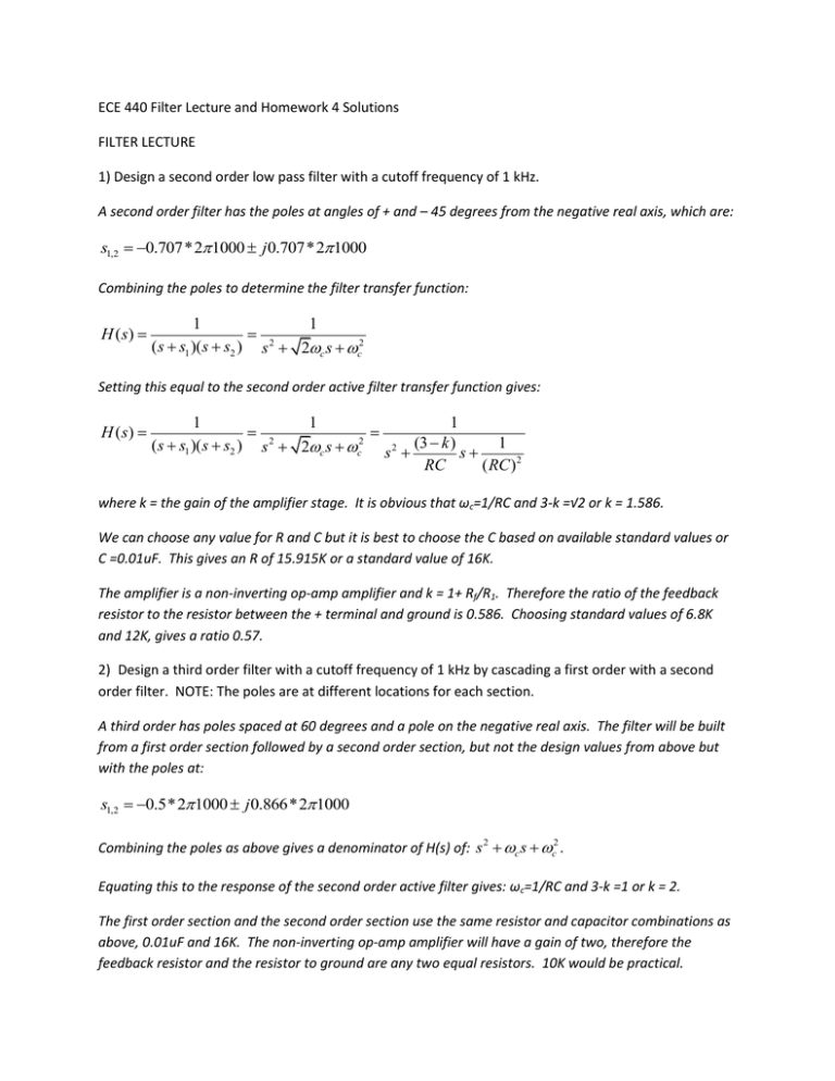
π π ω ω ω ω π π ω ω
advertisement

ECE 440 Filter Lecture and Homework 4 Solutions FILTER LECTURE 1) Design a second order low pass filter with a cutoff frequency of 1 kHz. A second order filter has the poles at angles of + and – 45 degrees from the negative real axis, which are: s1,2 0.707*2 1000 j 0.707*21000 Combining the poles to determine the filter transfer function: H ( s) 1 1 2 ( s s1 )( s s2 ) s 2c s c2 Setting this equal to the second order active filter transfer function gives: H (s) 1 1 1 2 2 ( s s1 )( s s2 ) s 2c s c s 2 (3 k ) s 1 RC ( RC ) 2 where k = the gain of the amplifier stage. It is obvious that ωc=1/RC and 3-k =√2 or k = 1.586. We can choose any value for R and C but it is best to choose the C based on available standard values or C =0.01uF. This gives an R of 15.915K or a standard value of 16K. The amplifier is a non-inverting op-amp amplifier and k = 1+ Rf/R1. Therefore the ratio of the feedback resistor to the resistor between the + terminal and ground is 0.586. Choosing standard values of 6.8K and 12K, gives a ratio 0.57. 2) Design a third order filter with a cutoff frequency of 1 kHz by cascading a first order with a second order filter. NOTE: The poles are at different locations for each section. A third order has poles spaced at 60 degrees and a pole on the negative real axis. The filter will be built from a first order section followed by a second order section, but not the design values from above but with the poles at: s1,2 0.5*2 1000 j 0.866*2 1000 Combining the poles as above gives a denominator of H(s) of: s 2 c s c2 . Equating this to the response of the second order active filter gives: ωc=1/RC and 3-k =1 or k = 2. The first order section and the second order section use the same resistor and capacitor combinations as above, 0.01uF and 16K. The non-inverting op-amp amplifier will have a gain of two, therefore the feedback resistor and the resistor to ground are any two equal resistors. 10K would be practical. 3) Design a fourth order filter with a cutoff frequency of 1 kHz by cascading two second order filters. NOTE: The poles are in different locations for each section. The poles on the fourth order filter would be spaced at 45 degrees starting at 22.5 degrees above and below the negative real axis: -67.5, -22.5, 22.5, and 67.5 degrees. The filter would be made of two second order sections, one after the other. Their order is not important. Their poles would be: s1,2 0.382*2 1000 j 0.924*21000 and s1,2 0.924*2 1000 j 0.382*21000 Combining these gives: s 2 0.764c s c2 and s 2 1.848c s c2 . Again the resistor and capacitors pairs for the filters are all the same: 0.01uF and 16K. The only difference between the two sections is the gain of the op-amp amplifier. In the first section 3-k=0.764 or k=2.236. This could be realized with a feed back resistor of 12k and a resistor to ground of 10k. In the second section, 3-k=1.848 or k =1.15. This could be realized with a feedback resistor of 15K and a resistor to ground of 100K. HOMEWORK 4 1) Design a low pass filter that has a pass band to 1000 Hz and the stop band begins at 12KHz with a minimum attenuation of -60 dB. Using the formula for stop band attenuation in a low pass Butterworth filter: Astop 1 f 1 stop fc 2N where N is the filter order, we can solve for N using Astop 60 1 f 1 stop fc 2N 10 20 103 which yields n=2.78. We must round UP to 3 to ensure our filter meets specifications. The design of the filter proceeds exactly as problem 2 in the filter lecture homework. 2) Design a low pass filter that has a pass band to 2000 Hz and the stop band begins at 30KHz with a minimum attenuation of -80dB. Using the procedure outlined above, the order of the filter can be determined as 3.4, rounded up to 4. The filter can be realized in two second order sections as outlined in problem 3 in the filter lecture homework. The gains for the inverting op-amp amplifiers will be exactly the same: 2.236 and 1.15. The R and C values to determine the cutoff frequency will be different and determined by: ωc=1/RC. Choosing 0.01uF again for C, R is7.96K, the nearest standard value is 8.2K. 3) Design a high pass filter that has a pass band beginning at 500 Hz and the stop band ends at 100 Hz with a minimum attenuation of -40 dB. In this case the design proceeds slightly differently. The attenuation formula for a HIGH pass Butterworth filter is: Astop 1 f 1 c f stop 2N giving an order of 2.8, rounded up to 3. The design can proceed for a third order filter can proceed as in the third order low pass filters outlined above. The difference is that the R and C resistors and capacitors switch places. The gain of the second order stage is the same as before and ωc=1/RC. Using 0.01uF again, R=31.831K or 33K for a standard value. 4) Design a bandpass filter that has a center frequency of 1000 Hz and a bandwidth of 100 Hz. This filter is defined by its center frequency, 1000Hz, and its Q which is the center frequency divided by the bandwidth or 10. C1 R3 R1 C2 Vi Vo + R2 0 We can choose a convenient capacitor of 0.01uF and, assuming C1= C2, calculate R3 using: R3 2Q which gives 318.3K, or the nearest standard value of 330K. To find R’, the parallel oC1 combination of R1 and R2, we use: R' R3 R which gives 795.8 ohms. The gain of this filter would be: A 3 or 207. To adjust the gain, 2 2R ' 4Q we would use R1 and R2 as a voltage divider and adjust their value so that the design gain is: A RR R2 while keeping R ' 1 2 795.8 . R1 R2 R1 R2 5) Design a bandpass filter that has a center frequency of 19KHz and a bandwidth of 1 KHz. This filter is defined by its center frequency, 19000Hz, and its Q which is the center frequency divided by the bandwidth or 19. We can choose a convenient capacitor of 0.001uF and, assuming C1= C2, calculate R3 using: R3 2Q which gives 159.2K, or the nearest standard value of 160K. To find R’, the parallel oC1 combination of R1 and R2, we use: R' R3 R which gives 110.2 ohms. The gain of this filter would be: A 3 or 726. To adjust the gain, 2 2R ' 4Q we would use R1 and R2 as a voltage divider and adjust their value so that the design gain is: A R2 RR while keeping R ' 1 2 110.2 . R1 R2 R1 R2 6) Design a Colpitts crystal controlled oscillator at 10MHz using a BJT. The crystal has a series resistance of 20 ohms and the BJT has a beta of 150 and is biased to have a gm of 0.0385. What values would you choose for the two capacitors in the feedback circuit? Q2 0 C1 1 Large L C2 2 0 If we use the rule of thumb to make the real part of the impedance looking into the Colpitts circuit from the emitter of the BJT to be 50 or 1299 ohms in this case, we can use that value in the formula: gm 1 C22 where R is the series resistance of the crystal, to calculate C2. In this case it gives 98.8 Re( Z i ) R pF, for which the nearest standard value is 100pF. To find the second capacitor, we need to look at the “transformer” action performed by C1 and C2, such that the “step up” ratio is: N C1 C2 . This forms the beta of our feedback loop back to the base. The amplifier is a common C1 collector with a gain of A Re 1 Re gm . Since Re=Re(Zi)=50/gm, the gain is 50/51 or0.98. Therefore to satisfy the oscillation criterion of A 1 , N would be 1.02. This would mean that C1 would be much larger than C2. In reality, the better value would be to make A 2 to ensure the oscillator starts. This would make C1 =C2.


