Philips
Networked Controls
part of the Dynalite family
HF Ballast Controller
DMBC320-DALI-NA
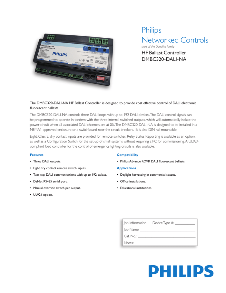
The DMBC320-DALI-NA HF Ballast Controller is designed to provide cost effective control of DALI electronic
fluorescent ballasts.
The DMBC320-DALI-NA controls three DALI loops with up to 192 DALI devices. The DALI control signals can
be programmed to operate in tandem with the three internal switched outputs, which will automatically isolate the
power circuit when all associated DALI channels are at 0%. The DMBC320-DALI-NA is designed to be installed in a
NEMA1 approved enclosure or a switchboard near the circuit breakers. It is also DIN rail mountable.
Eight, Class 2, dry contact inputs are provided for remote switches. Relay Status Reporting is available as an option,
as well as a Configuration Switch for the set-up of small systems without requiring a PC for commissioning. A UL924
compliant load controller for the control of emergency lighting circuits is also available.
Features
Compatibility
• Three DALI outputs.
• Philips Advance ROVR DALI fluorescent ballasts.
• Eight dry contact remote switch inputs.
Applications
• Two-way DALI communications with up to 192 ballast.
• Daylight harvesting in commercial spaces.
• DyNet RS485 serial port.
• Office installations.
• Manual override switch per output.
• Educational institutions.
• UL924 option.
Job Information
Device Type #: ___________
Job Name: ______________________________
Cat. No.: _______________________________
Notes:
Networked Controls
HF Ballast Controller (DMBC320-DALI-NA)
Technical data*
Supply: 120V-277VAC (+10%/-15%) 50/60Hz, Single Phase & Neutral.
Input power: Max 33W, Avg 24W
Input current: 120VAC max. 0.40A, 277VAC max. 0.15A
DALI power supply: Built-in internal DALI power supply 15VDC,
128mA rated per loop.
Short-circuit current max. 250mA per loop over-load protected.
DyNet DC supply: 500mA @24VDC
Relay output: 3 x 16A feed thru switched relay channels for DALI
ballast mains supply.
Voltage rating: Channel-to-channel: 480VAC, Channel-to-out: 277VAC,
8-24 AWG Cu wire.
DALI output terminals: 3 x DALI Loop, Low Voltage 12-22 AWG Cu
wire.
Preset scenes: 16 per Area.
Diagnostic functions:* Lamp failure reporting, Ballast failure reporting,
Ballast run time tracking for each ballast and the switched output,
Device Online/Offline status.
* MapView, Touch Screen or BAS interface required for analyzing diagnostic data. The
Mains outputs: 3 x 16A feed thru switched relay channels for DALI
ballast mains supply.
Compliance: UL/cUL Recognized, ICES, FCC, RoHS Compliant.
Relays: Latching type, lighting and resistive load rated.
availability of some diagnostics is dependent on the ballast type.
Control outputs: 3 x DALI Control Outputs, each supporting
a full DALI loop of 64 channels (192 total), including two-way
communication.
Operating environment: 32º to 104ºF (0º to 40ºC) ambient temp,
0% to 90% RH non condensing
Control inputs: 1 x RS485 DyNet serial port
8 x dry contact inputs (10VDC, 0.7mA)
Dimensions: H 5.6” x W 9.4” x D 2.0”
User controls: Service Switch, Diagnostic LED, Manual override switch
for each relay.
Supply terminals: Line, Neutral, Ground, 8-24 AWG Cu wire.
*Subject to change without notice.
Load compatibility
Load Type
Max Load
Electronic Ballast
16A, 120VAC
Electronic Ballast
16A, 277VAC
Construction: Lexan 920, UL94-VO
Weight: Packed weight 2.2 lbs.
Networked Controls
HF Ballast Controller (DMBC320-DALI-NA)
Mounting dimensions
Electrical diagram
Ordering information:
Ordering
Code
Description
DMBC320-DALI-NA
HF Ballast Controller
DMBC320DALI-EMG-NA
UL924 compliant Emergency Lighting DALI Ballast Controller
Quantity
©2012 Philips Lighting Electronics N.A.
A Division of Philips Electronics North America Corporation.
All rights reserved.
Published and printed in USA
February 2012
Form number: DS.DMBC320-DALI-NA.2.02242012
Philips Lighting
Customer Support: +1-800-526-2731
www.philips.com/lightingcontrolsna


