Lab 4 (Amplifier Design Using Operational Amplifiers
advertisement

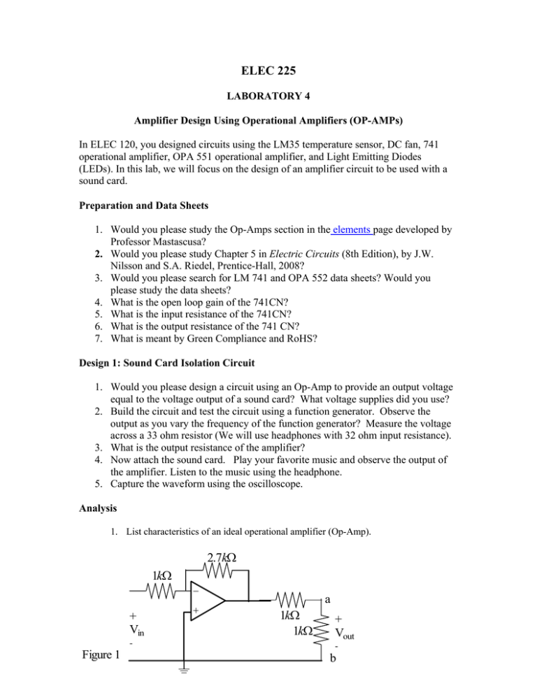
ELEC 225 LABORATORY 4 Amplifier Design Using Operational Amplifiers (OP-AMPs) In ELEC 120, you designed circuits using the LM35 temperature sensor, DC fan, 741 operational amplifier, OPA 551 operational amplifier, and Light Emitting Diodes (LEDs). In this lab, we will focus on the design of an amplifier circuit to be used with a sound card. Preparation and Data Sheets 1. Would you please study the Op-Amps section in the elements page developed by Professor Mastascusa? 2. Would you please study Chapter 5 in Electric Circuits (8th Edition), by J.W. Nilsson and S.A. Riedel, Prentice-Hall, 2008? 3. Would you please search for LM 741 and OPA 552 data sheets? Would you please study the data sheets? 4. What is the open loop gain of the 741CN? 5. What is the input resistance of the 741CN? 6. What is the output resistance of the 741 CN? 7. What is meant by Green Compliance and RoHS? Design 1: Sound Card Isolation Circuit 1. Would you please design a circuit using an Op-Amp to provide an output voltage equal to the voltage output of a sound card? What voltage supplies did you use? 2. Build the circuit and test the circuit using a function generator. Observe the output as you vary the frequency of the function generator? Measure the voltage across a 33 ohm resistor (We will use headphones with 32 ohm input resistance). 3. What is the output resistance of the amplifier? 4. Now attach the sound card. Play your favorite music and observe the output of the amplifier. Listen to the music using the headphone. 5. Capture the waveform using the oscilloscope. Analysis 1. List characteristics of an ideal operational amplifier (Op-Amp). 2.7kΩ 1kΩ a + Vin Figure 1 - 1kΩ 1kΩ + Vout - b 2. Determine (analytically) the Thevenin equivalent circuit looking to the left of terminals a and b as shown in Figure 1. Assume the operational amplifier is ideal. 3. Determine (experimentally) the Thevenin equivalent circuit looking to the left of terminals a and b as shown in Figure 1. Design 2: Voltage Amplifier As you might recall from ELEC 120, we analyzed the circuit shown in Figure 2. Now that you are more experienced, you might be able to appreciate the circuit a bit more!! RA R2 RB vin +12 V R1 vo − + −12 V RL Figure 2: Inverting amplifier 1. For the circuit in Figure 2, show that ⎛R ⎞R vo R = −⎜⎜ A + A + 1⎟⎟ 2 vin R R B ⎝ 2 ⎠ R1 R2 vin +12 V R1 − + vo −12 V RL Figure 3: Inverting amplifier. 2. For the circuit in Figure 3, show that vo R =− 2 vin R1 . 3. Simulate the circuit of Figure 3. Plot the input voltage vs. time and the output voltage vs. time. Let the input be a sine signal. Design 3: Amplifier Design for an 8-ohm Speaker 1. Design an amplifier to drive an 8-ohm speaker. What is the gain of your design? Why did you choose this gain? How would you change the gain of the amplifier? 2. Simulate your design? What is the power delivered to the speaker? 3. Build and test your design. 4. Now connect the sound to your design and listen to the music. Are you able to adjust the gain? Have a lot of fun!

