Ashcroft® Pressure Transducer Connection Instructions
For use with HOBO® H22, U12, U30, and UX120-006M data loggers and HOBO ZW data nodes
Applies to these Ashcroft Pressure Transducers:
Onset Part No.
Rating
Output
Ashcroft Part No.
T-ASH-G2-100
100 PSIG
0-5V representing 0 to 100 PSIG
G27M0205F2100#G-#4177
T-ASH-G2-200
200 PSIG
0-5V representing 0 to 200 PSIG
G27M0205F2200#G-#4177
T-ASH-G2-500
500 PSIG
0-5V representing 0 to 500 PSIG
G27M0205F2500#G-#4177
This document provides instructions on connecting the Ashcroft Pressure
Transducers listed above to each of the following:
•
FlexSmart™ Analog Module used with HOBO H22 series data loggers
•
Analog Sensor Port used with HOBO U30 series data loggers
•
Voltage adapter used with the U12 and UX120-006M data loggers and ZW
series data nodes
It also lists configuration values used by HOBOware® Pro software to configure the
logger for each transducer. Note: For information on connecting the pressure
transducer to the pressure source and other transducer details, refer to the
documentation provided by Ashcroft.
Ashcroft Pressure Transducer
Required:
• Selected Ashcroft Pressure Transducer
•
H22, U12, U30, or UX120-006M data logger, or HOBO ZW data node
•
FlexSmart Analog Module, Onset Part No. S-FS-CVIA (for H22 series); Analog Sensor Port option (for U30 series);
voltage adapter, Onset Part No. CABLE-ADAP5 (for U12, UX120-006M, or ZW series)
•
HOBOware Pro Software, version 2.2.1 or higher (2.4.0 or higher for U30 series; 3.0 or higher for ZW series; 3.6 or
higher for UX120-006M)
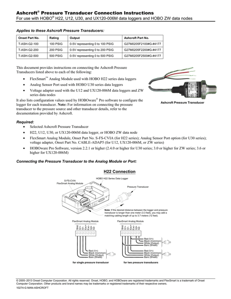
Connecting the Pressure Transducer to the Analog Module or Port:
H22 Connection
HOBO H22 Series Data Logger
S-FS-CVIA
FlexSmart Analog Module
Pressure Transducer
FlexSmart Analog Module
FlexSmart Analog Module
Shld
S1+
S1Exc+
ExcS2+
S2-
Shld
S1+
S1Exc+
ExcS2+
S2-
Note: If the desired distance between the logger and pressure
transducer is longer than one meter (3.3 feet), you may add a
matching cabling length of up to 3.7 meters (12 feet).
Red (V+)
Black (Common)
White (Output)
Bare (Shield)
Red (V+)
Black (Common)
White (Output)
Bare (Shield)
for single pressure transducer
Red (V+)
Black (Common)
White (Output)
Bare (Shield)
for two pressure transducers
© 2005–2013 Onset Computer Corporation. All rights reserved. Onset, HOBO, and HOBOware are registered trademarks and FlexSmart is a trademark of Onset
Computer Corporation. Other products and brand names may be trademarks or registered trademarks of their respective owners.
10274-G MAN-ASHCROFT
Ashcroft Pressure Transducer Connection Instructions
Shield
Ch1 Signal
Ch1 Return
Exc Out
HOBO U30 Series Data Logger
Analog Sensor Port
Pressure Transducer
Shield
Ch2 Signal
Ch2 Return
Ext Return
Analog Sensor Port
U30 Connection
Red (V+)
Black (Common)
White (Output)
Bare (Shield)
for single pressure transducer
Note: If the desired distance between the logger and pressure
transducer is longer than one meter (3.3 feet), you may add a
matching cabling length of up to 3.7 meters (12 feet).
Shield
Ch2 Signal
Ch2 Return
Ext Return
Shield
Ch1 Signal
Ch1 Return
Exc Out
Analog Sensor Port
Red (V+)
Black (Common)
White (Output)
Bare (Shield)
Red (V+)
Black (Common)
White (Output)
Bare (Shield)
for two pressure transducers
ZW, U12, and UX120-006M Connection
HOBO
ZW ZW
Series
Wireless
Data
Node;
U12
or UX120-006M
Logger
HOBO
Series
Wireless
Data
Node
or U12
Series Data Logger
(ZW shown)
Pressure Transducer
Note: If the desired distance between the logger and pressure
transducer is longer than one meter (3.3 feet), you may add a
matching cabling length of up to 3.7 meters (12 feet).
CABLE-ADAP5
Connect to analog port
AC-SENS-1*
CABLE-ADAP5
N/C
White (+)
*CAUTION: Polarity is very
important! Before plugging
AC-SENS-1 into AC power,
make sure the correct
polarity lead connections to
device are made as shown!
Bare (Shield)
White (Output)
Black (-)
(Red wire not used)
Black (Common)
Red (V+)
Use appropriate termination for all
connections (denoted with )
AC-SENS-1*
(+)
(-)
Configuring the Data Logger for the Pressure Transducer, using HOBOware Pro Software:
HOBOware Pro software provides configuration files for the transducers. The table below lists the recommended configuration
values for each transducer that these files contain. For information on loading configuration files, refer to the software
documentation.
Onset Part No.
Channel
Name
Warm-Up*
Measurement
Type
Raw
Value 1
Raw
Value 2
Raw
Units
Scaled
Value 1
Scaled
Value 2
Scaled
Units
T-ASH-G2-100
Pressure
0.03 sec
Voltage
0
5
V
0
100
PSIG
T-ASH-G2-200
Pressure
0.03 sec
Voltage
0
5
V
0
200
PSIG
T-ASH-G2-500
Pressure
0.03 sec
Voltage
0
5
V
0
500
PSIG
* Excitation power provided by the FlexSmart Analog Module (Onset Part No. S-FS-CVIA) with H22; by the Analog Sensor Port with U30; and
by power adapter (Onset Part No. AC-SENS-1) with ZW, U12, or UX120-006M.
Page 2 of 2


