Model 7190 Dual Digital Barometer User`s Manual
advertisement
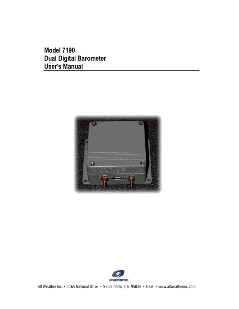
Model 7190 Dual Digital Barometer User's Manual All Weather Inc. • 1165 National Drive • Sacramento, CA 95834 • USA • www.allweatherinc.com User's Manual 7190 Dual Digital Barometer CONTENTS CONTENTS..................................................................................................................................I THEORY OF OPERATION ..........................................................................................................1 Introduction ............................................................................................................................1 Pressure Sensor ....................................................................................................................1 Measurement principle...........................................................................................................2 Block diagram ........................................................................................................................3 INSTALLATION & CHECKOUT....................................................................................................4 Mounting ................................................................................................................................4 Pressure connections ............................................................................................................5 MAINTENANCE ...........................................................................................................................5 Periodic Maintenance ............................................................................................................5 Equipment Required........................................................................................................5 Monthly Maintenance ......................................................................................................5 Quarterly Maintenance ....................................................................................................5 Debris/Obstruction Removal .....................................................................................6 Pressure Port Vent Cleaning ....................................................................................6 Barometric Pressure Check ......................................................................................6 Barometric Pressure Adjustment (AWOS) ................................................................6 Annual Maintenance........................................................................................................6 Altimeter Setting Check ............................................................................................6 SPECIFICATIONS........................................................................................................................7 Barometric pressure ........................................................................................................7 Electronics.......................................................................................................................7 Mechanics .......................................................................................................................7 ELECTROMAGNETIC COMPATIBILITY .....................................................................................8 Emissions...............................................................................................................................8 Immunity ................................................................................................................................8 WARRANTY .................................................................................................................................9 AWOS WARRANTY .....................................................................................................................9 Page i User's Manual 7190 Dual Digital Barometer Theory of Operation INTRODUCTION The Model 7190 Dual Digital Barometer is a fully compensated digital barometer designed to cover a wide environmental pressure and temperature range. It can be used successfully both in accurate pressure measurement applications at room temperature and in demanding automatic weather stations applications. The 7190 digital barometer uses a silicon capacitive absolute sensor. The sensor has excellent hysteresis and repeatability characteristics, a low temperature dependence and a very good long-term stability. The ruggedness of the sensor is outstanding. The measurement principle of the 7190 digital barometer is based on an advanced RC oscillator and three reference capacitors against which the capacitive pressure sensor and the capacitive temperature compensation sensor are continuously measured. The microprocessor of the barometer performs compensation for pressure linearity and temperature dependence. The basic pressure and temperature adjustment of the pressure transducers in the 7190 digital barometer consists of seven temperature levels over the operating temperature range of the barometer and of seven to nine pressure levels over the operating pressure range of the barometer at each temperature level. The calculated individual basic pressure and temperature adjustment coefficients are stored in the EEPROM of each pressure transducer. The user cannot change these basic factor adjustments. The 7190 digital barometer has two pressure transducers. Two pressure transducers provide for a self-diagnostic feature: the user can set alarm limits within which the pressure transducers must remain for reliable measurement. The 7190 barometer can also be configured to measure two separate pressures. The user can define various applications, specific settings, such as serial bus settings, averaging time, output interval, output format, pressure unit and pressure resolution. It is also possible to select different sending modes at power-up such as free running mode, stand-by mode and a mode with one automatically sent message. A fast measurement mode with ten measurements per second can also be selected. The factory settings have been chosen so that both a fast settling time is not required, longer averaging times are recommended to reduce environmental pressure noise. In addition to the standard RS 232C full duplex and bi-directional TTL level serial interface the user can select either an RS 485/422 two wire half duplex serial interface or a pulse output interface with user selectable pulse rate, pressure resolution and pressure offset. The 7190 digital barometer is traceable to National Institute of Standards and Technology (NIST) in the USA. PRESSURE SENSOR The 7190 barometers use a silicon capacitive absolute pressure sensor for barometric pressure measurement applications. This sensor has excellent hysteresis and repeatability characteristics, a low temperature dependence and a very good long-term stability. The ruggedness of the sensor is outstanding, and the sensor is resistant to mechanical and thermal shocks. Page 1 7190 Dual Digital Barometer User's Manual Figure 1 Pressure Sensor The pressure sensor (Figure 1) consists of two layers of single crystal silicon with a layer of glass between them. The thinner silicon layer is etched on both sides to create an integral vacuum reference chamber for the absolute pressure sensor and to form a pressure sensitive silicon diaphragm. The thicker silicon layer is the rigid base plate of the sensor and it is clad with a glass dielectric. The thinner pierce of silicon is electrostatically bonded to the glass surface to form a strong and hermetic bond. Thin film metallization has been deposited to form a capacitor electrode inside the vacuum reference chamber; the other electrode is the pressure sensitive silicon diaphragm. The coefficients of thermal expansion of silicon and glass materials used in the pressure sensor are carefully matched together to minimize the temperature dependence and to maximize the long-term stability. The pressure sensor is designed to achieve zero temperature dependence at 1000 hPa and its long-term stability has been maximized by thermal aging at an elected temperature. The capacitive pressure sensor features a wide dynamic range and no self-heating effect. The excellent hysteresis and repeatability characteristics are based on the ideal spring characteristics of single crystal silicon. In the pressure sensor, the silicon material is exerted to only few percent of its whole elastic range. MEASUREMENT PRINCIPLE The measurement principle of the 7190 digital barometer is based on an advanced RC oscillator with three reference capacitors against which the capacitive pressure sensor and the capacitive temperature compensation sensor are continuously measured. A multiplexer connects each of the five capacitors to the RC oscillator one at a time and five different frequencies are measured during one measurement cycle, Figure 2. One capacitance measurement lasts about 3 ms and the total measurement cycle lasts about 15 ms. The RC oscillator is designed to attenuate changes in stray impedances and to achieve an excellent measurement stability with time. This electronic measurement principle emphasizes in the first place stability over a wide environmental temperature and relative humidity range and over a long period of time; yet it can achieve quite fast speed at the same time. Page 2 User's Manual 7190 Dual Digital Barometer Figure 2 RC oscillator with five capacitors In the fast measurement mode a special measurement algorithm is used. In this mode only the frequency from the pressure sensor is measured continuously while the frequencies from the three reference capacitors and from the thermal compensation capacitor are updated only every 30 seconds. This is quite justifiable as the changes in the reference capacitors can be considered negligible over any period of time and the temperature compensation reading can change only very slightly inside the heavy metal housing of the 7190 digital barometer over a few tens of seconds. The fast measurement mode achieves a speed of ten measurements per second at 1 Pascal resolution; i.e. each measurement represents the pressure average during the last 100 ms. When the reference frequencies are measured every 30 seconds the outputting stops for a short moment and typically one measurement is lost during this time. BLOCK DIAGRAM The 7190 digital barometer consists of a CPU board and 2 pressure transducers. The pressure transducers are typically connected to the same pressure port. However, the barometer can have two pressure ports, one for each transducer. The 7190 barometer always has an RS 232C full duplex and a bi-directional TTL level serial interface. In addition, the barometer has either a pulse output interface or an RS 485/422 two-wire half duplex serial interface. The RS 485/422 interface is a separate optional module inside the barometer. This interface module is order specific and installed at the factory. For the basic block diagram of the 7190 barometer, see Figure 3. Page 3 7190 Dual Digital Barometer Figure 3 User's Manual Block diagram of the Model 7190 barometer INSTALLATION & CHECKOUT MOUNTING In automatic weather station applications, the 7190 digital barometer has to be installed inside a weather resistant enclosure. The user must also pay attention to the fact that the pressure fitting supplied with the barometer is not a static pressure head. The barbed pressure fitting is not recommended for turbulent or high speed static wind conditions; the accuracy quoted for the 7190 digital barometer does not include any wind effects. The pressure fitting must also be carefully protected from rain as falling water may get into the pressure connector and cause errors in the pressure measurement. These wind and rain effects can be eliminated by using the quad plate pressure port available from All Weather Inc.. (All All Weather Inc. AWOS systems include the M105037 Quad Plate Pressure Port.) In benign room temperature conditions, i.e. in laboratory measurements, no further environmental protection is required. In all cases, special attention should be paid to the grounding of the barometer. The main dimensions and recommended mounting positions of the 7190 barometer are shown in Figure 4. Page 4 User's Manual 7190 Dual Digital Barometer Fig. 4 Dimensions and mounting positions of 7190 barometer PRESSURE CONNECTIONS The barometer is equipped with a standard Clippard 11752-1 barbed pressure fitting with 10-32 external thread installed in the barometer. This fitting is ideal for an 1/8” internal diameter tubing. If some other pressure fitting need to be used, it is possible to replace the standard barbed fitting. The pressure connection in the barometer housing has a metric M5 internal thread which is compatible with a non-metric 10-32 internal thread. The barbed pressure fitting is not recommended for turbulent or high speed static wind conditions: the accuracy quoted for the 7190 digital barometer does not include any wind effects. The pressure fitting must also be carefully protected from rain as falling water may get into the pressure connector and cause errors in the pressure measurement. The 7190 barometer is designed to measure the pressure of clean, non-condensing, non-conducting and non-corrosive gases only. Maintenance PERIODIC MAINTENANCE Periodic maintenance of the Model 7190 is divided into three categories within the maintenance cycle: monthly, quarterly, and annual maintenance procedures. Equipment Required Equipment required for periodic maintenance of the Model 7190 consists of: • Model 7101 pressure standard Monthly Maintenance Monthly maintenance of the Model 7190 consists of visually checking the pressure port and clearing any debris from within the plate area. Quarterly Maintenance Quarterly maintenance consists of: • Debris/obstruction removal • Pressure port vent cleaning Page 5 7190 Dual Digital Barometer User's Manual • Barometric pressure check • Barometric pressure adjustment (AWOS) Debris/Obstruction Removal Visually check the pressure port and clear any debris from within the plate area. Pressure Port Vent Cleaning 1 Remove the quad plate pressure port drain plug (the Phillips screw on the underside of the bottom plate) using a Phillips screwdriver, and drain any accumulated moisture. 2 Remove both flexible tubes from the barometer inlets and blow gently into the tubes to clear any accumulated debris. 3 Replace the tubes and drain plug. Barometric Pressure Check Using the Model 7101 pressure standard, compare the output of the pressure sensor with the standard. The values may differ by 0.02 in Hg or less and still be within tolerance. With AWOS systems, the readings are to be adjusted as necessary to be within ±0.005 in Hg of the standard as explained below. Note the amount of deviation of the Model 7190 from the standard; this will be used as the adjustment value. Barometric Pressure Adjustment (AWOS) Following the barometric pressure check outlined above, sensors used in AWOS systems must be adjusted as necessary to within ±0.005 in Hg of the standard. (Exception: Adjustments of more than 0.05 in Hg are not allowed. If the sensor differs from the standard by more than 0.05 in Hg, replace the sensor.) To adjust the sensor: 1 Enter barometric pressure correction mode on the CDP. 2 Enter the adjustment value obtained above during the barometric pressure check. 3 Note the cumulative adjustment for each sensor. Annual Maintenance Annual maintenance consists of performing the procedures outlined for quarterly maintenance, along with an altimeter setting check, and recording the results on the annual data form. Altimeter Setting Check Use the formula below to calculate Altimeter Setting from the barometric pressure measured using the Model 7101 pressure standard. Record the calculated altimeter setting and that reported by the AWOS on the annual data form. 5.25486 Alt.Setting (inHg)= (BPα + SE ⋅1.313⋅10−5 ) ⋅100 ( where: α = 0.1903 SE = Sensor elevation above sealevel in feet BP = Barometric pressurein inHg Page 6 ) User's Manual 7190 Dual Digital Barometer Specifications Barometric pressure Operating Range Pressure range Operating temperature range Storage temperature range Humidity range Accuracy Linearity * Hysteresis * Repeatability* Calibration uncertainty ** Temperature dependence *** Long-term stability Total including one year drift * ** *** 500-1100hPa -40 to +60ºC -60 to +60ºC non-condensing ± 0.05hPa ± 0.03 hPa ± 0.03 hPa ± 0.08 hPa ± 0.1 hPa ± 0.1 hPa/year ± 0.20 hPa Defined at the ± standard deviation limits of end-point non-linearity, hysteresis error or repeatability error. Defined as ± standard deviation limits of inaccuracy of the working standard at 1000 hPa in comparison to international standards (NIST). Defined as ±2 standard deviation limits of temperature dependence over the operating temperature range. Electronics (* factory settings) Supply voltage Supply voltage sensitivity Current consumption Pressure units Resolution Setting time at power-up one sensor Response time one sensor fast measurement mode Acceleration sensitivity 10-35 VDC, reverse polarity protected negligible < 25 mA (continuous operation mode) < 0.1 mA (hardware shutdown mode) hPa*, kPa, Pa, mbar, inHg, mmHg, torr, psia 0.01 hPa* 2 seconds* 500 ms* 100 ms* negligible Mechanics Pressure connector Pressure fitting Maximum pressure limit Minimum pressure limit Electrical connector Housing Weight Dimensions M5 (10-32) internal thread barbed fitting for 1/8” I.D. tubing (Clippard 11752-1 hose fitting) 5000 hPa abs. 0 hPa female 9-pin sub-D connector epoxy painted aluminum 1 kg 5.71" W x 4.72" H x 2.56" D (145 mm x 120 mm x 65 mm) Page 7 7190 Dual Digital Barometer User's Manual Electromagnetic compatibility The 7190 barometer is designed to comply with the CE norms for electromagnetic compatibility. The condition for this compliance is the use of braided cables and proper grounding techniques. The 7190 barometer has successfully passed the following emission and immunity tests: EMISSIONS Test: Radiated interferences Setup according to: EN55022 (class B) IMMUNITY Test: Electrostatic discharge Electrical fast transients RF radiated fields Page 8 Setup according to: IEC 1000-4-2 IEC 1000-4-4 IEC 1000-4-3 Performance: criteria B criteria B criteria A User's Manual 7190 Dual Digital Barometer Warranty Unless specified otherwise, All Weather Inc. (the Company) warrants its products to be free from defects in material and workmanship under normal use and service for one year from date of shipment, subject to the following conditions: (a) The obligation of the Company under this warranty is limited to repairing or replacing items or parts which have been returned to the Company and which upon examination are disclosed, to the Company’s satisfaction, to have been defective in material or workmanship at time of manufacture. (b) The claimant shall pay the cost of shipping any part or instrument to the Company. If the Company determines the part to be defective in material or workmanship, the Company shall prepay the cost of shipping the repaired instrument to the claimant. Under no circumstances will the Company reimburse claimant for cost incurred in removing and/or reinstalling replacement parts. (c) This warranty shall not apply to any Company products which have been subjected to misuse, negligence or accident. (d) This warranty and the Company’s obligation thereunder is in lieu of all other warranties, express or implied, including warranties of merchantability and fitness for a particular purpose, consequential damages and all other obligations or liabilities. No other person or organization is authorized to give any other warranty or to assume any additional obligation on the Company’s behalf, unless made in writing and signed by an authorized officer of the Company. AWOS WARRANTY This equipment has been manufactured and will perform in accordance with requirements of FAA Advisory Circular 150/5220-16B. Any defect in design, materials, or workmanship which may occur during proper and normal use during a period of 1 year from date of installation or a maximum of 2 years from shipment will be corrected by repair or replacement by All Weather Inc. Page 9 All Weather Inc. 1165 National Drive Sacramento, CA 95818 Fax: 916.928.1165 Phone: 916.928.1000 Toll Free: 800.824.5873 Phone: +49-(0)2102-80193/80221 7190-001 ECN 4777
