SR Relay Operation
advertisement

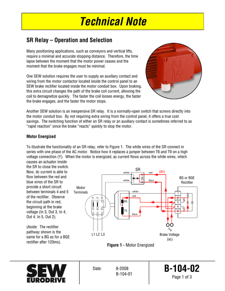
Technical Note SR Relay – Operation and Selection Many positioning applications, such as conveyors and vertical lifts, require a minimal and accurate stopping distance. Therefore, the time lapse between the moment that the motor power ceases and the moment that the brake engages must be minimal. One SEW solution requires the user to supply an auxiliary contact and wiring from the motor contactor located inside the control panel to an SEW brake rectifier located inside the motor conduit box. Upon braking, this extra circuit changes the path of the brake coil current, allowing the coil to demagnetize quickly. The faster the coil looses energy, the faster the brake engages, and the faster the motor stops. Another SEW solution is an inexpensive SR relay. It is a normally-open switch that screws directly into the motor conduit box. By not requiring extra wiring from the control panel, it offers a true cost savings. The switching function of either an SR relay or an auxiliary contact is sometimes referred to as “rapid reaction” since the brake “reacts” quickly to stop the motor. Motor Energized To illustrate the functionality of an SR relay, refer to Figure 1. The white wires of the SR connect in series with one phase of the AC motor. Notice how it replaces a jumper between T6 and T9 on a high voltage connection (Y). When the motor is energized, ac current flows across the white wires, which causes an actuator inside the SR to close the switch. SR (dc) Now, dc current is able to red white flow between the red and BG or BGE white blu e blue wires of the SR to Rectifier provide a short circuit Motor white between terminals 4 and 5 Terminals 1 red of the rectifier. Observe T4 T5 T6 2 BS the circuit path in red, 3 4 beginning at the brake T7 T8 T9 TS 5 voltage (In 3, Out 3, In 4, blu e T1 T2 T3 Out 4, In 5, Out 2). (Aside: The rectifier pathway shown is the same for a BG as for a BGE rectifier after 120ms). VB L1 L2 L3 Brake Voltage (ac) Figure 1 - Motor Energized Date: 8-2008 B-104-01 B-104-02 Page 1 of 3 Technical Note Motor De-Energized At the moment the motor power ceases, the energy stored in the brake coil must discharge as quickly as possible. Therefore, when the SR actuator detects zero current at the motor terminals, it re-opens the SR switch, as shown in Figure 2. Since terminal 3 has no available pathway for current to flow, residual energy within the brake coil cannot flow through the red coil wire. Also, since terminals 4 and 5 are no longer connected, coil energy cannot flow through terminal 5. So, the coil energy must flow through terminal 4 and across a varistor that dissipates the energy quickly, which rapidly demagnetizes the coil. The concurrent removal of AC current from the brake-supply voltage and DC current from terminals 4 and 5 is commonly referred to as “cut-off in the DC and AC circuit” represented by symbol at right. white SR white Motor Terminals red T5 BG or BGE Rectifier blu e 1 2 3 4 5 red T6 BS T7 T8 T9 T1 T2 T3 AC (dc) white T4 DC TS blu e Figure 2: Motor De-energized Varistor VB L1 L2 L3 Brake Voltage (ac) Important Notes • SR relay cannot be used with an inverter! Since inverters vary the voltage signal to the motor, the voltage to the SR relay may not be high enough for proper operation. The correct product for an inverter application is a UR relay. It receives a constant supply voltage directly from the control panel, not from the motor terminals. • SR relay cannot replace a UR relay. Even though SR and UR relays both screw into the motor conduit box and look nearly identical, they are not interchangeable. The SR relay is a current sensor that receives power from the motor terminal. The UR relay is a voltage sensor that receives separate power from the control panel. If a UR relay were to be incorrectly connected to motor terminals in a vertical lifting application, a considerably large stopping distance may occur. The reason is because a hoisting motor acts a generator when power ceases. Therefore, the UR relay detects positive voltage instead of zero voltage and does not function properly. Date: 8-2008 B-104-01 B-104-02 Page 2 of 3 Technical Note SR Selection The following table lists the assignment of SR relays per motor and motor voltage. DT56M...BMG DT56L...BMG DR63S...BR DR63M...BR DR63L...BR DT71D...BMG DT80K...BMG DT80N...BMG DT90S...BMG DT90L...BMG DT100LS…BMG DT100L….BMG DV100M...BMG DV100L...BMG DV112M...BMG DV132S...BMG DV132M...BM DV132ML...BM DV160M...BM DV160L...BM DV180M...BM DV180L...BM DV200L...BM DV225S...BM DV225M...BM DV250M...BMG DV280S...BMG DV280M...BMG 523-690 465-522 415-464 370-414 330-369 294-329 262-293 234-261 208-233 186-207 165-185 148-164 132-147 117-131 105-116 93-104 83-92 74-82 67-73 59-66 Motor 40-58 AC Motor Voltage in Y wiring (ex: 230YY/460Y, 230Δ/400Y) SR10 SR11 SR15 Not Available SR19 Per Technical Data 09 856 04 93. Date: 8-2008 B-104-01 B-104-02 Page 3 of 3


