ET 255 Using Photovoltaics: Grid connected or Stand
advertisement
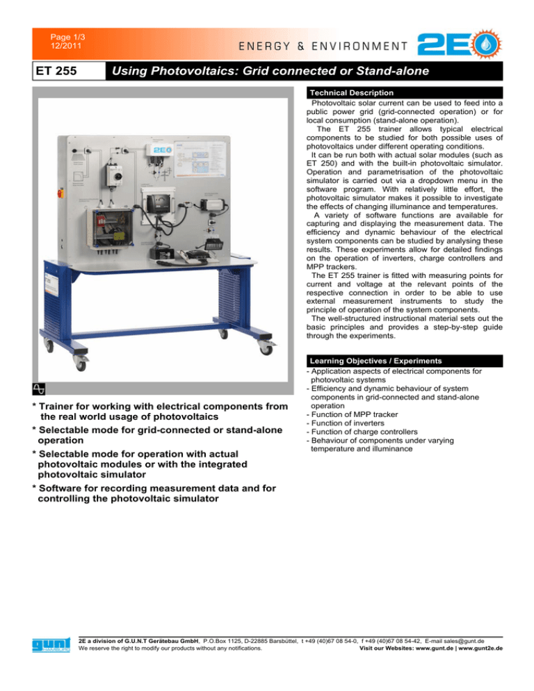
Page 1/3 12/2011 ET 255 Using Photovoltaics: Grid connected or Stand-alone Technical Description Photovoltaic solar current can be used to feed into a public power grid (grid-connected operation) or for local consumption (stand-alone operation). The ET 255 trainer allows typical electrical components to be studied for both possible uses of photovoltaics under different operating conditions. It can be run both with actual solar modules (such as ET 250) and with the built-in photovoltaic simulator. Operation and parametrisation of the photovoltaic simulator is carried out via a dropdown menu in the software program. With relatively little effort, the photovoltaic simulator makes it possible to investigate the effects of changing illuminance and temperatures. A variety of software functions are available for capturing and displaying the measurement data. The efficiency and dynamic behaviour of the electrical system components can be studied by analysing these results. These experiments allow for detailed findings on the operation of inverters, charge controllers and MPP trackers. The ET 255 trainer is fitted with measuring points for current and voltage at the relevant points of the respective connection in order to be able to use external measurement instruments to study the principle of operation of the system components. The well-structured instructional material sets out the basic principles and provides a step-by-step guide through the experiments. * Trainer for working with electrical components from the real world usage of photovoltaics c * Selectable mode for grid-connected or stand-alone operation c * Selectable mode for operation with actual photovoltaic modules or with the integrated photovoltaic simulatorc * Software for recording measurement data and for controlling the photovoltaic simulator Learning Objectives / Experiments - Application aspects of electrical components for photovoltaic systems - Efficiency and dynamic behaviour of system components in grid-connected and stand-alone operation - Function of MPP tracker - Function of inverters - Function of charge controllers - Behaviour of components under varying temperature and illuminance 2E a division of G.U.N.T Gerätebau GmbH, P.O.Box 1125, D-22885 Barsbüttel, t +49 (40)67 08 54-0, f +49 (40)67 08 54-42, E-mail sales@gunt.de Visit our Websites: www.gunt.de | www.gunt2e.de We reserve the right to modify our products without any notifications. Page 2/3 12/2011 ET 255 Using Photovoltaics: Grid connected or Stand-alone Specification [1] Trainer with electrical components from practical usage of photovoltaics [2] Operation with photovoltaic simulator or actual photovoltaic modules [3] Grid-connected or stand-alone operation [4] Inverter with MPP tracker for grid-connected operation [5] Inverter and replaceable charge controller for stand-alone operation [6] Solar battery and lamp for stand-alone operation [7] Commercially available combiner box [8] LabVIEW software for data acquisition and comtrol of the photovoltaic simulator via USB under Windows XP or Windows Vista 1 module temperature and illuminance connection socket, 2 symbol for photovoltaic simulator, 3 photovoltaic module connection socket, 4 toggle switch: photovoltaic simulator/photovoltaic module, 5 combiner box, 6 DC switch-disconnector, 7 toggle switch: grid-connected/stand-alone, 8 inverter with MPP tracker (grid-connected), 9 charge controller with MPP tracker (stand-alone), 10 inverter (stand-alone), 11 solar battery (stand-alone), 12 lamp (stand-alone), 13 charge controller without MPP tracker (stand-alone, removable) Technical Data Photovoltaic simulator: - max. output: approx. 150W - short-circuit current: approx. 5A - open-circuit voltage: approx. 50V Inverter for grid-connected operation: - rated input power: 150W - max. output power: 125W - max. efficiency: 89% Charge controller for stand-alone operation: - charging current: 20A - end charging voltage: approx. 14V Dimensions and Weight LxBxH: 1560 x 790 x 1760mm Weight:: ca. 110 kg Connections 230V, 50/60Hz, 1 Phase Wiring Diagram: A photovoltaic module, B photovoltaic simulator, C combiner box, D DC main switch - components for grid-connected operation: E inverter with MPP tracker, F mains connection - components for stand-alone operation: G charge controller, H solar battery, I inverter, J lamp; - toggle switches: 1 photovoltaic simulator/photovoltaic module, 2 grid-connected/stand-alone Scope of Delivery 1 trainer 1 charge controller with MPP tracker for stand-alone operation 1 charge controller without MPP tracker (shunt charge controller) for stand-alone operation 1 set of cables 1 set of instructional materials 1 LabVIEW software CD + USB cable Order Details 06125500 ET 255 Using Photovoltaics: Grid connected or Stand-alone 2E a division of G.U.N.T Gerätebau GmbH, P.O.Box 1125, D-22885 Barsbüttel, t +49 (40)67 08 54-0, f +49 (40)67 08 54-42, E-mail sales@gunt.de Visit our Websites: www.gunt.de | www.gunt2e.de We reserve the right to modify our products without any notifications. Page 3/3 12/2011 ET 255 Using Photovoltaics: Grid connected or Stand-alone Available Accessories Product no. Order text 061.25000 ET 250 Solar Module Measurements 2E a division of G.U.N.T Gerätebau GmbH, P.O.Box 1125, D-22885 Barsbüttel, t +49 (40)67 08 54-0, f +49 (40)67 08 54-42, E-mail sales@gunt.de Visit our Websites: www.gunt.de | www.gunt2e.de We reserve the right to modify our products without any notifications.
