I(x,t)
advertisement

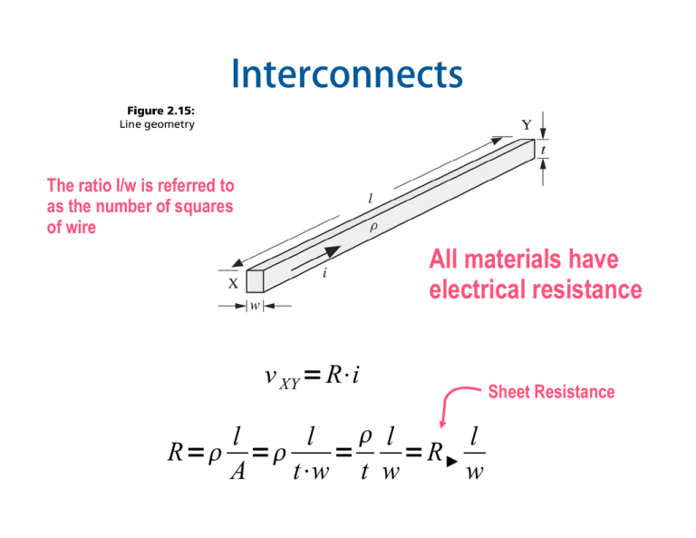
Interconnects The ratio l/w is referred to as the number of squares of wire All materials have electrical resistance v XY Ri l l l l R R A tw t w w Sheet Resistance Resistance To keep the resistance of long wire small we must make its width big It takes 4 times more chip area Resistivity Resistivity depends on temperature Sheet Resistance Silicide: process of coating a material with a refractory metal such as tugsten to decrease the overall resistivity A refractory material is one that retains its strength at high temperatures Polysilicon and Diffusion have high resistance (even if silicided) Polysilicon and Diffusion • Diffusion has high resistance and high capacitance (about 2 fF/μm: comparable to gate capacitance) • Avoid diffusion (runners) for wires ! • Polysilicon has lower capacitance but still high resistance • Use for transistor gates • Only occasionally for very short wires between gates Resistance of Contacts and Vias • Contacts and vias have resistance associated with them (2 – 20 ) • Use multiple small contacts rather a single large contact when the current turns at right angle use more contacts Interconnects A conducting line patterned on top of an insulating layer creates a capacitance w.r.t. the silicon substrate ins C wl t ins dv iC dt Changing the capacitor voltage by an amount v requires a time interval: C t v i In other words there is a delay in the transmission of the electric signal Fringe Capacitance Multilayer Capacitance •Line to to Line capacitance •Overlap capacitance C total C b o tC top 2 C a d j C gnd C b o tC top Crosstalk • Delay effects • Noise Effects Modeling a single interconnect line l R t w ins C wl t ins Simple RC lumped model ins 2 2 RC l l t t ins The time delay on an RC line is proportional to the square of its length Delay and Rise Time of a simple RC V inp t V pulseu t V out t V pulse 1et Lumped vs. Distributed RC model • In reality the resistance and capacitance of the line is distributed along its entire length Improving the lumped-element RC model • Placing the capacitance at the end overestimate its effect RC 1 RC 2 Lumped vs. Distributed Delay Vin(t) = u(t) Lumped approximations • The L model is a very poor choice • The and T model are equivalent • It is common practice to model long wires with 3- or 4- segments Delay through a distributed RC Distributed RC: analytical approach (1) I(x+x,t) I(x,t) + + V(x,t) V(x+x,t) – – x x+x V x , t V x x , t R d I x , t V x x , t I x , t I x x , t C d t Distributed RC: analytical approach (2) C d , R d ? ??? Capacitance and resistance per unit length Capacitance and resistance of a single distributed cell C C u C d C u x l R R d Ru x Ru l V x , t V x x , t R u x I x , t V x x , t I x , t I x x , t C u x t V x , t V x x , t Ru I x , t x I x , t I x x , t V x x , t C u t x Distributed RC: analytical approach (3) V x , t V x x R u I x , t x I x , t I x x V x x C u t x • If we let x 0 ( and recall that: V x ,t R u I x , t x I x ,t V x ,t C u x t f ' xlim h 0 f xh f x ) h V R I u x x x 2 V V R C u u 2 t x Distributed RC: analytical approach (4) Diffusion Equation Does not have a closed form solution !!! 2 V x , t R C V x , t 2 2 t x l The input voltage is applied at x=0 Using an input of V(0,t) = Vpu(t) the solution at any point x is: V x ,t V Perfc x 2 RC ut 2 l t With: erfc 1erf erf 2 e d 0 2 2 e d 2 erf 00 erf 1 erf erf 2 e d erfc d 2 Practical interconnect modeling • The driver is modeled by a voltage source and its source resistance R1 • The medium wire is modeled by a single segment • The long wire is modeled by two -segments Elmore Delay approximation • For a general RC network we compute the Elmore delay as: i C k Rik k • where: – the node of interest is node i – Ck is the capacitance at node k – Rik is the sum of all resistances in common from the source to node i and the source to node k Example of Elmore Delay Calculation D3= C1 R1+ C2 (R1+R2) + C3 (R1+R2+R3) + C4 R1 D4 = C1 R1 + C2 R1 + C3 R1 + C4 (R4 + R1) Distributed RC: approximated approach • Assume the line has N sections and use Elmore approximation: C R C R R C R R R ... N terms N N N N N N N N N N RC CR CR CR N N 1 2 12... N 2 i 2 N 2 2 N N i1 N Improving interconnect delay through repeaters Summary: important results • Step Response of lumped and distributed RC networks Voltage Range Lumped RC Distributed RC 050% (tp) 0.69 RC 0.38 RC 063% () RC 0.5 RC 10%90% (tr) 2.2 RC 0.9 RC 090% 2.3 RC 1.0 RC Design Rules of Thumbs • w.r.t. propagation delay – RC effects should be considered only when the propagation delay of the interconnect is comparable or larger than the propagation delay of the driving gate Lcrit • t pgate 0.38 RC l 2 RC delays become dominant for interconnect wires longer than Lcrit w.r.t. rise (fall) time – RC effects should be considered only when the rise (fall) time at the line's input is smaller than the rise (fall) time of the line (0.9 RC) t rise 0.9 RC If this condition occurs the RC delay is such that the line cannot keep up with the rate of change of the signal applied to it


