Sheet Resistance: Measurement and Significance
advertisement

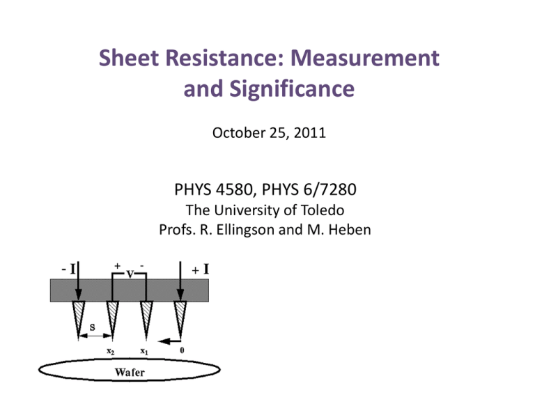
Sheet Resistance: Measurement and Significance October 25, 2011 PHYS 4580, PHYS 6/7280 The University of Toledo Profs. R. Ellingson and M. Heben Sheet Resistance Regular 3-D conductor, resistance R is: L L R=ρ =ρ A Wt where ρ is the resistivity (Ω⋅m), A is the cross-section area, and L is the length. For A in terms of W and t, ρ L L = Rs R= t W W • where Rs is the Sheet Resistance. Units are ohms, but can also express this as “ohms per square, or Ω/⃞, or Ω/sq. A square sheet with an Rs of 100 Ω/⃞ has a resistance of 100 Ω (regardless of the size of the square). http://en.wikipedia.org/wiki/Sheet_resistance Four point probe: Theory (bulk sample) For a bulk sample (thickness t >> s, where s is the probe spacing), a spherical current from the outer probe tips is assumed: Differential resistance given by: dx ΔR = ρ A where ρ is the resistivity, dx is the differential length, and A is the surface area penetrated by the current from one probe. To determine the resistance between the voltage measurement tips, one integrates between x1 and x2: x2 R= ρ x1 dx ρ 1 1 ρ = = − 2πx 2 2π x x1 2 s 2π Superposition of current at outer two tips leads to R = V/2I, so that ρ = 2πs(V/I) http://www.fourpointprobes.com/four-point_probe.html x2 Four point probe: Theory (thin sheet) For a thin film sample (thickness t << s), we have the case of current rings, so that A = 2πxt. R= x2 x1 2s dx dx ρ ρ 2s (ln x ) s = ln 2 ρ = ρ = s 2πxt 2πxt 2πt 2πt As before, superposition of current at outer two tips leads to R = V/2I, so that the sheet resistivity for a thin film sample is: ρ= πt V ln 2 I The expression is not dependent on s. Sheet Resistivity is defined as: Rs = ρ V = k t I k is a geometric factor, which for a semi-infinite thin film is π/(ln 2) = 4.53 http://www.fourpointprobes.com/four-point_probe.html Goals of the Transparent Conductors Unit 1) Use the optical system to measure the transmission, reflection and absorbance from three Cr films and two TEC glass samples, at near-normal incidence. 2) Measure and report on the film thickness using the Dektak profilometer for the thickest Cr film. Based on your transmission measurements of all three Cr films, what do you predict as the thickness of the two thinner Cr films which you were unable to measure on the Dektak? 3) Use the four point probe to measure and report on the sheet resistance values for each of the five transparent conducting samples. For the Cr films, what do you predict as the thicknesses of the two thinner films based on the Dektak film thickness measurement for the thickest film and the sheet resistance values for all three films? Explain briefly how a film of (for example) half the thickness of another may not show a sheet resistance twice that of the thicker film. 4) Describe the interplay between transparency and sheet resistance for the 3 Cr film samples, and separately for the 2 TEC glass substrates. 5) Of the five films you have examined, which would function best as the top contact of a solar cell, and why?


