8:MBP
June 2007
Specification Sheet
Modbus Protocol Emulation Program
The Modbus Protocol Emulation Program is designed
to allow a ROC300-Series Remote Operations
Controller with a ROCPAC or FlashPAC, or a
FloBoss™ 407 Flow Manager to emulate the Modbus
protocol. This makes it possible to integrate the ROC
or FloBoss into a Modbus host/slave system.
The Modbus program is loaded and configured with
ROCLINK™ 800 Configuration Software. The program
can be configured to emulate several Modbus protocol
variations. In addition to acting as a Modbus slave, the
ROC can function as a Modbus host (master) with the
ability to poll Modbus slave devices. A port with
Modbus master enabled may still act as a slave
device. Either the American Standard Code for
Information Interchange (ASCII) or the Remote
Terminal Unit (RTU) mode of transmission can be
used.
Modbus Compatibility
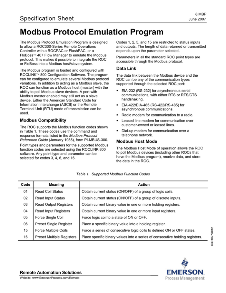
The ROC supports the Modbus function codes shown
in Table 1. These codes use the command and
response formats listed in the Modbus Protocol
Reference Guide (January 1985), form PI-MBUS-300.
Point types and parameters for the supported Modbus
function codes are selected using the ROCLINK 800
software. Any point type and parameter can be
selected for codes 3, 4, 6, and 16.
Codes 1, 2, 5, and 15 are restricted to status inputs
and outputs. The length of data returned or transmitted
depends upon the parameter selected.
Parameters in all the standard ROC point types are
accessible through the Modbus protocol.
Data Link
The data link between the Modbus device and the
ROC can be any of the communication types
supported through the selected ROC port:
EIA-232 (RS-232) for asynchronous serial
communications, with either RTS or RTS/CTS
handshaking.
EIA-422/EIA-485 (RS-422/RS-485) for
asynchronous communications.
Radio modem for communication to a radio.
Leased line modem for communication over
customer-owned or leased lines.
Dial-up modem for communication over a
telephone network.
Modbus Host Mode
The Modbus Host Mode of operation allows the ROC
to poll Modbus devices (including other ROCs that
have the Modbus program), receive data, and store
the data in the ROC.
Table 1. Supported Modbus Function Codes
Meaning
Action
01
Read Coil Status
Obtain current status (ON/OFF) of a group of logic coils.
02
Read Input Status
Obtain current status (ON/OFF) of a group of discrete inputs.
03
Read Output Registers
Obtain current binary value in one or more holding registers.
04
Read Input Registers
Obtain current binary value in one or more input registers.
05
Force Single Coil
Force logic coil to a state of ON or OFF.
06
Preset Single Register
Place a specific binary value into a holding register.
15
Force Multiple Coils
Force a series of consecutive logic coils to defined ON or OFF states.
16
Preset Multiple Registers
Place specific binary values into a series of consecutive holding registers.
Remote Automation Solutions
Website: www.EmersonProcess.com/Remote
D301027X012
Code
8:MBP
Page 2
Specification Sheet
The data can be used for parameter updates, FST
program registers, and other variables. This allows a
user-written program to control the polling performed
by the ROC. The ROC host can also send commands
to set outputs and to write data to a slave device.
ROC Point Types
Parameters in all the standard ROC point types are
accessible through the Modbus protocol. These point
types are listed in the following table.
Data Transmission Modes
Type
Two modes of data transmission are available for use
in a Modbus system: ASCII and RTU. Both modes
provide the same capabilities for communicating with
the Modbus host and are selected depending on the
equipment used. All devices in the communication
network must be configured with the same mode of
transmission.
0
1
2
3
4
5
6
7
9
10
11
12
13
14
15
16
17
18
19
20
22, 23
25-39
40
41
42
43
44
56
57
In RTU mode, data is sent in 8-bit binary characters. In
ASCII mode, each 8-bit character is split into two
hexadecimal numbers, which are then converted into
ASCII printable characters.
Modbus Configuration
After you select the Modbus Protocol program for a
ROC communication port (typically COM1 or COM2)
and load it into the ROC, you can configure it. The
Modbus functionality is configured for the selected port
using up to four displays, which are accessed from the
Configure menu (see Figure 1).
Description
Configurable Opcode
Discrete Inputs
Discrete Outputs
Analog Inputs
Analog Outputs
Pulse Inputs
PID Control
AGA Flow Parameters
Local Display Panel1
AGA Flow Values
Tank Parameters
ROC Clock
System Flags
Communications Ports
System Variables
FST Registers
Soft Points
AI Calibration
Database Setup
ROC Tasks
User-defined
User-defined
MVS Parameters1,2
AGA Run Parameters1,2
Extra AGA Run Parameters1,2
User Lists2
Power Control2
AI Calibration1,2
Keypad/Log-on Parameters1,2
1
ROC300-Series with FlashPAC.
2
FloBoss 407.
Media
Figure 1. ROCLINK 800 User Data Menu
for Modbus
The Modbus program and user manual are supplied
on a CD-ROM
Bristol, Inc., Bristol Babcock Ltd, Bristol Canada, BBI SA de CV and the Flow Computer Division, are wholly owned subsidiaries of Emerson Electric Co. doing
business as Remote Automation Solutions (“RAS”), a division of Emerson Process Management. FloBoss, ROCLINK, Bristol, Bristol Babcock, ControlWave,
TeleFlow and Helicoid are trademarks of RAS. AMS, PlantWeb and the PlantWeb logo are marks of Emerson Electric Co. The Emerson logo is a trademark and
service mark of the Emerson Electric Co. All other marks are property of their respective owners.
The contents of this publication are presented for informational purposes only. While every effort has been made to ensure informational accuracy, they are not to
be construed as warranties or guarantees, express or implied, regarding the products or services described herein or their use or applicability. RAS reserves the
right to modify or improve the designs or specifications of such products at any time without notice. All sales are governed by RAS’ terms and conditions which
are available upon request. RAS does not assume responsibility for the selection, use or maintenance of any product. Responsibility for proper selection, use and
maintenance of any RAS product remains solely with the purchaser and end-user.
Emerson Process Management
Remote Automation Solutions
Marshalltown, IA 50158 U.S.A.
Houston, TX 77041 U.S.A.
Pickering, North Yorkshire UK Y018 7JA
© 1992-2007 Remote Automation Solutions, division of Emerson Process Management. All rights reserved.

