Manual - Patlite
advertisement

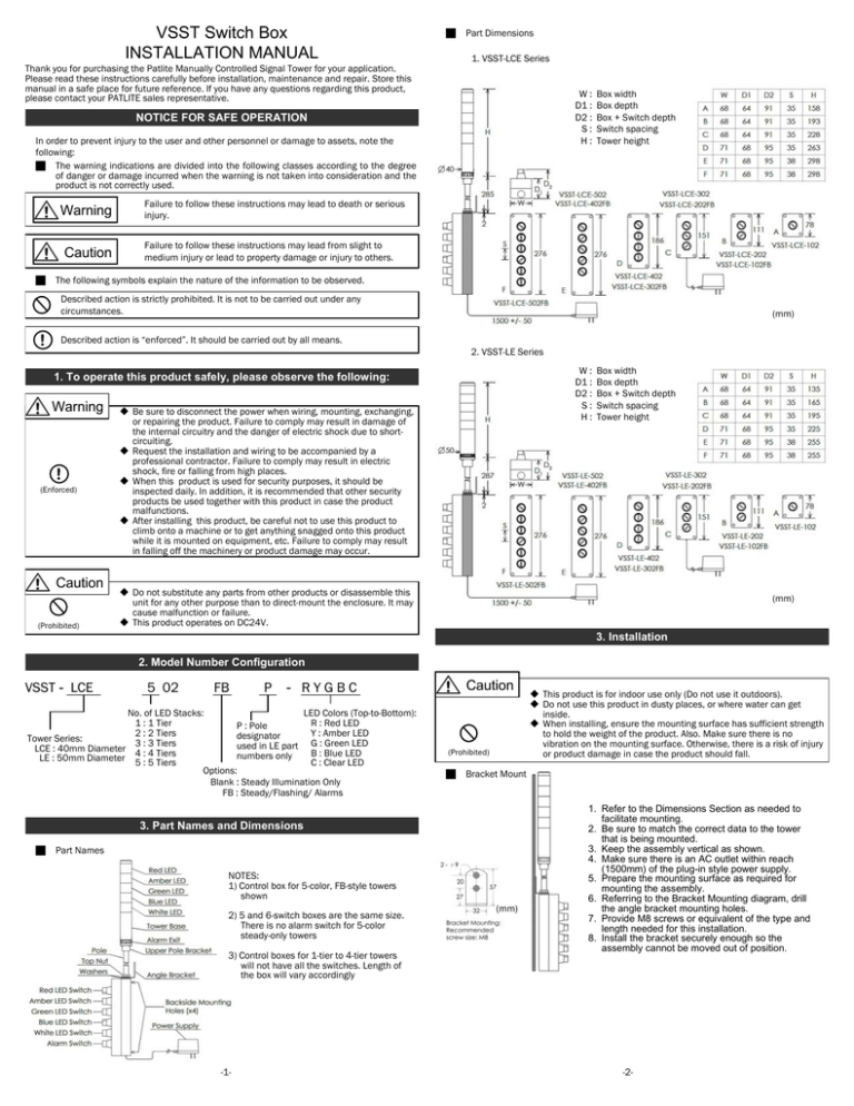
VSST Switch Box INSTALLATION MANUAL Part Dimensions 1. VSST-LCE Series Thank you for purchasing the Patlite Manually Controlled Signal Tower for your application. Please read these instructions carefully before installation, maintenance and repair. Store this manual in a safe place for future reference. If you have any questions regarding this product, please contact your PATLITE sales representative. W: D1 : D2 : S: H: NOTICE FOR SAFE OPERATION In order to prevent injury to the user and other personnel or damage to assets, note the following: The warning indications are divided into the following classes according to the degree of danger or damage incurred when the warning is not taken into consideration and the product is not correctly used. Warning Caution Box width Box depth Box + Switch depth Switch spacing Tower height Failure to follow these instructions may lead to death or serious injury. Failure to follow these instructions may lead from slight to medium injury or lead to property damage or injury to others. The following symbols explain the nature of the information to be observed. Described action is strictly prohibited. It is not to be carried out under any circumstances. ! (mm) Described action is “enforced”. It should be carried out by all means. 2. VSST-LE Series W: D1 : D2 : S: H: 1. To operate this product safely, please observe the following: Warning ! (Enforced) Caution (Prohibited) Be sure to disconnect the power when wiring, mounting, exchanging, or repairing the product. Failure to comply may result in damage of the internal circuitry and the danger of electric shock due to shortcircuiting. Request the installation and wiring to be accompanied by a professional contractor. Failure to comply may result in electric shock, fire or falling from high places. When this product is used for security purposes, it should be inspected daily. In addition, it is recommended that other security products be used together with this product in case the product malfunctions. After installing this product, be careful not to use this product to climb onto a machine or to get anything snagged onto this product while it is mounted on equipment, etc. Failure to comply may result in falling off the machinery or product damage may occur. Box width Box depth Box + Switch depth Switch spacing Tower height Do not substitute any parts from other products or disassemble this unit for any other purpose than to direct-mount the enclosure. It may cause malfunction or failure. This product operates on DC24V. (mm) 3. Installation 2. Model Number Configuration VSST - LCE 5 02 FB P - RYGBC No. of LED Stacks: LED Colors (Top-to-Bottom): 1 : 1 Tier R : Red LED P : Pole 2 : 2 Tiers Y : Amber LED designator Tower Series: 3 : 3 Tiers used in LE part G : Green LED LCE : 40mm Diameter 4 : 4 Tiers B : Blue LED numbers only LE : 50mm Diameter 5 : 5 Tiers C : Clear LED Options: Blank : Steady Illumination Only FB : Steady/Flashing/ Alarms Caution (Prohibited) Bracket Mount 3. Part Names and Dimensions Part Names NOTES: 1) Control box for 5-color, FB-style towers shown 2) 5 and 6-switch boxes are the same size. There is no alarm switch for 5-color steady-only towers 3) Control boxes for 1-tier to 4-tier towers will not have all the switches. Length of the box will vary accordingly -1- This product is for indoor use only (Do not use it outdoors). Do not use this product in dusty places, or where water can get inside. When installing, ensure the mounting surface has sufficient strength to hold the weight of the product. Also. Make sure there is no vibration on the mounting surface. Otherwise, there is a risk of injury or product damage in case the product should fall. (mm) 1. Refer to the Dimensions Section as needed to facilitate mounting. 2. Be sure to match the correct data to the tower that is being mounted. 3. Keep the assembly vertical as shown. 4. Make sure there is an AC outlet within reach (1500mm) of the plug-in style power supply. 5. Prepare the mounting surface as required for mounting the assembly. 6. Referring to the Bracket Mounting diagram, drill the angle bracket mounting holes. 7. Provide M8 screws or equivalent of the type and length needed for this installation. 8. Install the bracket securely enough so the assembly cannot be moved out of position. -2- Box Mount Caution (Prohibited) Caution Do not operate the switches with excessive force. There is the risk of breaking the switch components. Before proceeding to install using the Box-Mount method, check that the tower has sufficient clearance so it does not contact the wall. (Prohibited) 6. Specifications 1. On the front cover, back out the captive screw at each corner and separate the front & back half of the box. 2. Loosen the pole nut if necessary and turn the angle bracket 90O either direction. Be careful not to over-tighten the nut as it may break the enclosure. 3. Choose a configuration so that the tower will not interfere with the vertical mounting surface. 4. Make sure there is an AC outlet within reach (1500mm) of the plug-in style power supply. 5. See the dimensions provided to position and drill the mounting holes. 6. Mount the box by inserting user-supplied mounting hardware into the holes provided through the back half of the box. 7. Keep the front & back half of the box aligned and tighten the captive screws at each corner. Be careful not to pinch the wiring. 3 2 5 6 1 7 4 LED Light Tower Operation without Flashing / Alarm Capability 1. Plug in the wall-plug-style power supply into the AC outlet supplying the correct AC voltage level per the specifications of this product. 2. Each switch is color-coded to correspond to the color of the corresponding LED light on the tower. 3. Turn the 3-position rotary switch on the enclosure to the left to turn on the tower light in steady mode. 4. Turn the 3-position rotary switch on the enclosure to the center to turn the tower light OFF. 5. Turn the 3-position switch to the right to turn on the tower light in flashing mode. 6. Turn the gray 3-position switch on the enclosure to the left to select Alarm 1 (fast beep) 7. Turn the gray 3-position switch on the enclosure to the center to turn the alarm off. 8. Turn the gray 3-position switch on the enclosure to the right to select Alarm 2 (slow beep) DC24V (No polarity) Operating Voltage Rated Voltage +/- 10% Mounting Location Indoor use only, Flat wall surface without vibration Caution (Prohibited) PATLITE Corporation disclaims all liability for any malfunction or damage that occurs as a result of handling contrary to the instructions, cautions and warnings mentioned in this manual. Specifications may change without notice due to continual product improvement. Limited Warranty: PATLITE (U.S.A) CORPORATION ("PATLITE") warrant its products to be free from defects in material and workmanship under normal and proper use for a period of one (1) year from the initial date of shipment by PATLITE. In the even of a defect not caused by misuse or damage to the products, PATLITE will, at its option, repair, replace or return the purchase price for, defective products upon PATLITE's inspection. THIS WARRANTY IS IN LIEU OF AND EXCLUDES ALL OTHER WARRANTIES, REMEDIES AND CONDITIONS, WHETHER EXPRESS, IMPLIED OR STATUTORY, INCLUDING WITHOUT LIMITATION ANY IMPLIED WARRANTIES OF MERCHANTABILITY AND FITNESS FOR A PARTICULAR PURPOSE. IN NO EVENT SHALL PATLITE OR THE MANUFACTURER BE LIABLE FOR ANY SPECIAL, INCIDENTAL OR CONSEQUENTIAL DAMAGES, INCLUDING LOSS OF PROFITS OR "DOWN TIME" DAMAGES, WHETHER ARISING FROM NEGLIGENCE, TORT, STRICT LIABILITY, CONTRACT, WARRANTY OR OTHERWISE. IN NO EVENT SHALL PATLITE OR THE MANUFACTURER BE LIABLE FOR PUNITIVE OR EXEMPLARY DAMAGES. 1500mm 5. Operation Rated Voltage PATLITE USA Corporation 20130 S. Western Avenue Torrance, CA 90501 TEL: 888-214-2580 FAX: 310-328-2676 Web Site: www.patlite.com Sales: sales@patlite.com LED Light Tower Operation with Flashing / Alarm Capability 1. Plug in the wall-plug-style power supply into the AC outlet supplying the correct AC voltage level per the specifications of this product. 2. Each switch is color-coded to correspond to the color of the corresponding LED light on the tower. 3. Turn the 3-position rotary switch on the enclosure to the left to turn on the tower light in steady mode. 4. Turn the 3-position rotary switch on the enclosure to the center to turn the tower light OFF. 5. Turn the 3-position switch to the right to turn on the tower light in flashing mode. 6. Turn the gray 3-position switch on the enclosure to the left to select Alarm 1 (fast beep) 7. Turn the gray 3-position switch on the enclosure to the center to turn the alarm off. 8. Turn the gray 3-position switch on the enclosure to the right to select Alarm 2 (slow beep) -3- -4-


