R
HYDROMATIC Q-ALERT ALARM
®
liquid level alarm systems
Versatile, Indoor or Outdoor
w w w.HYDROMATIC.com
Q-ALERT ALARM
liquid level alarm systems
Versatile, Indoor Or Outdoor
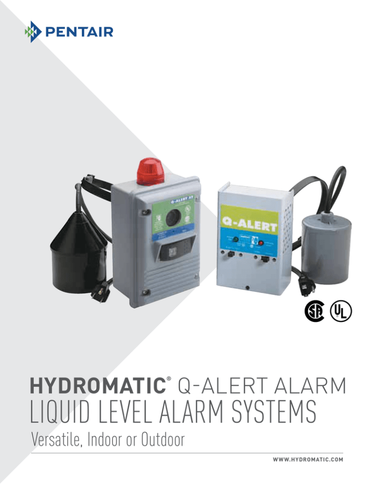
Q-ALERT – indoor alarm system
Q-ALERT XT – outdoor alarm system
Applications
These quality alarm systems are designed to pro­vide a
de­pend­able high or low liquid level warning device for
residential ­and ­­­­­commercial applications. The Q-ALERT XT
alarm can serve as a high or low level alarm de­pend­ing
on the float switch model used. A potentially threatening
liquid level condition is announced by an alarm horn
and a red beacon which can be seen from all directions.
Common applications include lift pump chambers,
sump pump basins, holding tank sew­age systems, and
irrigation systems.
Indoor Model: Q-Alert
Features
•Automatic alarm reset
•Alarm silence switch
•Alarm test switch
•Alarm system (when installed on separate circuit) operates even
if pump circuit fails
•Complete package includes standard Sensor Float® control
switch with 15 feet (4.6 meters) of cable and pipe clamp for
mounting and 6 foot (1.8 meter) power cord
•UL Listed
•CSA Certified
•Two-year limited war­ran­ty
Options
Indoor/Outdoor Model: Q-Alert XT
This alarm is available:
• With auxiliary dry contacts for easy attachment of remote
de­vices
• Premounted terminal block so enclosure can also be used as a
junction box for splicing pump, pump switch, and power
Q-ALERT ALARM
Installation Instructions
WARNING
To avoid serious or fatal electrical shock, turn off power source before installing or
ad­just­ing this device.
A qualified service person must install this product according to national and local
elec­tri­cal codes. Do not install in haz­ard­ous locations as defined by the National
Electrical Code, ANSI/ NFPA 70.
Installing the Float Switch
Determine desired activation level (see Figure A). To adjust activation level, move
pipe clamp up or down on discharge pipe.
2
Tighten pipe clamp around the discharge pipe at desired ­­­activation level. Keep
switch cable between strap and pipe to help prevent slippage (see Figure B).
3
To lock releasable tab, run remaining strap between re­leas­able tab and head.
Pull tightly.
4
To eliminate obstruction to switch, tuck strap back through clamp head
(see Figure B).
Installing The Alarm
1
Mount alarm box using existing holes in back of box. To ensure water-tight seal,
use screws and sealing washers included with alarm.
2
Determine “conduit-in” locations on alarm (see Figure C). Note: When used with a
pump application, connect alarm to circuit breaker separate from pump circuit. This
allows alarm to continue to operate if pump circuit should fail.
4
Drill holes for conduit entry, taking care not to damage bosses inside the alarm box.
5
Bring float switch cable through conduit and wire to terminal strip positions Fl and
F2 on alarm cover (see Figure C).
6
Wire “power-in” conductors to terminal strip positions L1 (line) and N (neutral) and
ground wire to ground termination post (see Figure C). Note: If terminal block option
is used, attach ground wire to left terminal 4 as shown in Figure A of Terminal Block
Option Installation Instructions.
7
If remote device is used, connect to terminal strip for optional auxiliary dry contacts
as shown in Figure C.
8
Connect wire leads from circuit board to beacon as shown in Figure C.
9
Attach alarm box cover using the four preinstalled screws.
10
Turn on power.
11
Check installation by manually tipping float switch. The alarm horn and beacon
should indicate an alarm condition.
13
Figure B
secure cable
between strap
and pipe
clamp
head
Attach conduit.
If alarm includes remounted terminal block option, refer now to the Terminal
Block Option Installation Instructions.
12
approximate
activation level
Push silence switch to test silence feature.
Test unit periodically to ensure proper operation.
releasable tab
Figure C
connect wire leads
for beacon
ground
termination
post
recommended
normally open
common
normally closed
3
Figure A
float (F2)
float (F1)
line (L1)
neutral (N)
1
recommended
power
float switch
conduit-in conduit-in
location
location
terminal strip for
optional auxiliary
dry contacts
Q-ALERT ALARM
Specifications
Voltage
120 VAC, 50/60 Hz, 7 watts max. (alarm condition)
Enclosure
6.5 inch x 4.5 inch x 3.0 inch (16.51 cm x 11.43 cm x 7.62 cm), indoor and outdoor, weatherproof
thermoplastic.
Auxiliary Alarm Contacts
(optional): 5 amps, 120 VAC, 50/60 Hz
Alarm Horn
82 decibels at 10 feet (3 meters)
Alarm Float
Sensor Float® control switch with pipe clamp
Cable
15 feet (4.57 meters) of flexible 16 gauge, 2 conductor SJOW-A (UL), SJOW (CSA), water-resistant,
neoprene (CPE)
Housing
3.38 inch diameter x 4.55 inch long (8.58 cm x 11.56 cm), impact resistant, noncorrosive, PVC plastic
for use in liquids up to 140˚F (60˚C)
Switch
Reliable float switch rated for minimum 250,000 cycles
Dimension Data - Q-Alert
Dimension Data - Q-Alert Xt
4” 1/8
(104.85)
6”
7” 1/2
(190.5)
(152.4)
4” 3/4
2” 1/4
(120.65)
(57.15)
All dimensions in inches. Metric for international use. Component dimensions
may vary ± 1/8 inch. Dimensional data not for construction purpose unless
certified. Dimensions and weights are approximate. On/Off level adjustable. We
reserve the right to make revisions to our product and their specifications without
(2 instances) notice.
4” 1/8
(104.78)
All dimensions in inches. Metric for international use. Component dimensions
may vary ± 1/8 inch. Dimensional data not for construction purpose unless
certified. Dimensions and weights are approximate. On/Off level adjustable. We
reserve the right to make revisions to our product and their specifications without
(2 instances) notice.
USACANADA
293 Wright Street, Delavan, WI 53115 WWW.HYDROMATIC.COM
269 Trillium Drive, Kitchener, Ontario, Canada N2G 4W5
PH: 888-957-8677 ORDERS FAX: 800-426-9446
PH: 519-896-2163 ORDERS FAX: 519-896-6337
Because we are continuously improving our products and services, Pentair reserves the right to change specifications without prior notice.
© 2012 Pentair Ltd. All Rights Reserved.
W-02-6930 (11/20/12)


