Introduction to Radio Wave Polarization
advertisement
Introduction to Radio Wave Polarization
Whitham D. Reeve
1. Introduction
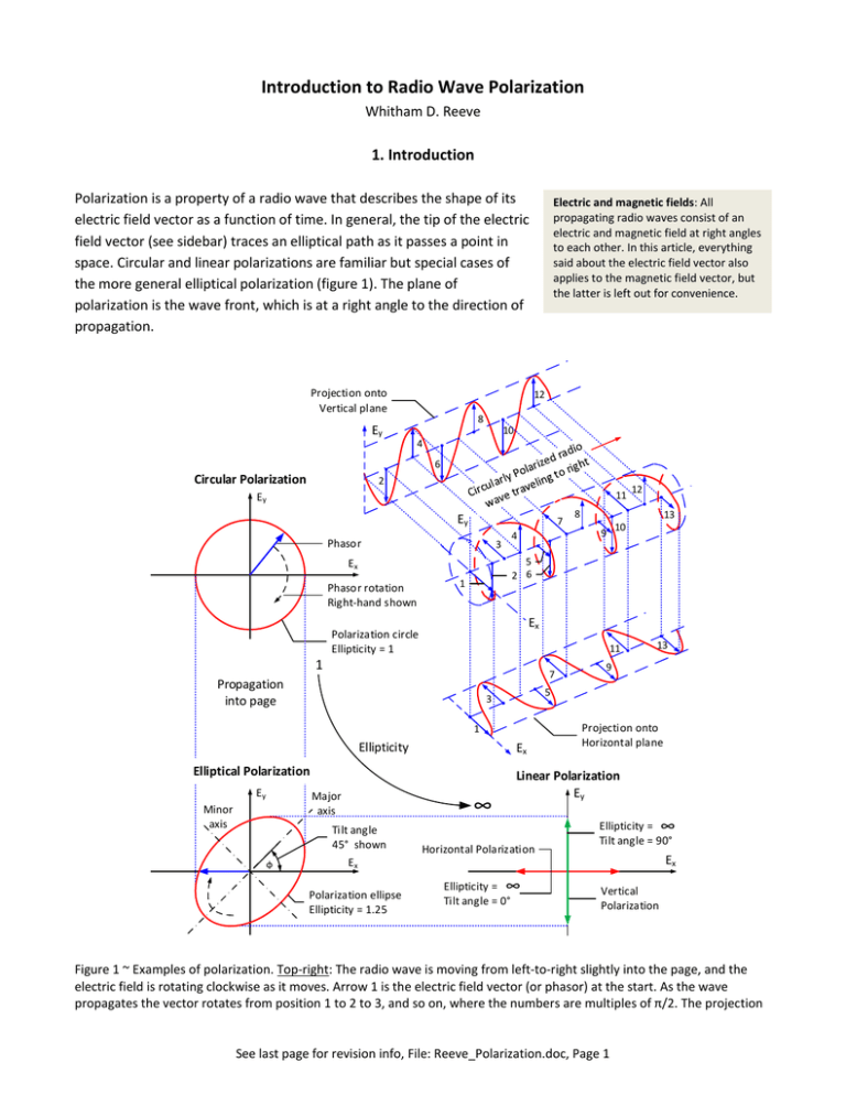
Polarization is a property of a radio wave that describes the shape of its
electric field vector as a function of time. In general, the tip of the electric
field vector (see sidebar) traces an elliptical path as it passes a point in
space. Circular and linear polarizations are familiar but special cases of
the more general elliptical polarization (figure 1). The plane of
polarization is the wave front, which is at a right angle to the direction of
propagation.
Projection onto
Vertical plane
Ey
Electric and magnetic fields: All
propagating radio waves consist of an
electric and magnetic field at right angles
to each other. In this article, everything
said about the electric field vector also
applies to the magnetic field vector, but
the latter is left out for convenience.
12
8
10
4
6
Circular Polarization
2
11
Ey
Ey
7
Phasor
3
1
1
11
7
1
Ellipticity
Ex
Elliptical Polarization
Minor
axis
∞
Tilt angle
45° shown
Ex
Polarization ellipse
Ellipticity = 1.25
13
9
5
3
Major
axis
9
Ex
Polarization circle
Ellipticity = 1
Propagation
into page
Ey
13
10
5
2 6
Ex
Phasor rotation
Right-hand shown
4
8
12
Projection onto
Horizontal plane
Linear Polarization
Ey
Horizontal Polarization
Ellipticity = ∞
Tilt angle = 0°
Ellipticity = ∞
Tilt angle = 90°
Ex
Vertical
Polarization
Figure 1 ~ Examples of polarization. Top-right: The radio wave is moving from left-to-right slightly into the page, and the
electric field is rotating clockwise as it moves. Arrow 1 is the electric field vector (or phasor) at the start. As the wave
propagates the vector rotates from position 1 to 2 to 3, and so on, where the numbers are multiples of π/2. The projection
See last page for revision info, File: Reeve_Polarization.doc, Page 1
of the electric field amplitude on a horizontal plane with vectors 1, 3, 5 . . . is shown immediately below as the horizontal
component of the elliptically polarized wave. The projection on a vertical plane with vectors 2, 4, 5 . . . is shown to the left.
Note the 90° (π/2) phase difference between the horizontal and vertical projections. Top-left: If the ellipse has equal major
and minor axes, it would be a circle, and the wave would be circularly polarized. Bottom-left: The ellipse indicates the line
traced by the tip of the electric field vector as it rotates and moves into the page. Bottom-right: If the ellipse minor axis is
zero and major axis has some value, the path traced by the electric vector would be a straight line, and the wave would
have linear polarization. Both horizontal and vertical polarizations are shown. (Image © 2014 W. Reeve)
The electric and magnetic fields associated with an elliptically polarized radio wave rotate in the plane of
polarization at a rate related to the radio wave’s frequency. The electric vector completes one revolution in the
period = 1/frequency while simultaneously varying in amplitude. As will be discussed in section 2, any radio
wave can be decomposed into two perpendicular field components, for example, horizontal and vertical.
Elliptical polarization results whenever the components have different phases or different amplitudes. In this
case, the field is never zero because the two components do not pass through zero at the same time. In antenna
engineering the shape of the ellipse is described by its ellipticity, which is the ratio of the ellipse major and minor
axes. This ratio also is called axial ratio.
A wave with linear polarization has an ellipticity of infinity (minor axis is zero) and circular polarization has an
ellipticity of one (major and minor axes are the same). The electric vector of a vertically polarized wave points in
a vertical direction with respect to a reference such as Earth’s surface, whereas a horizontally polarized wave is
perpendicular to the vertical wave and points parallel to Earth’s surface. Horizontal and vertical are arbitrary
orientations in terms of celestial radio waves, which can take on any orientation. Polarizations of celestial radio
waves are discussed in section 4. The electric field vector of a radio wave with elliptical or circular polarization
rotates. Right-hand circular polarization (RHCP) or right-hand elliptical polarization (RHEP) means the vector
rotates clockwise when viewed toward the direction of propagation. Left-hand circular polarization (LHCP) or
left-hand elliptical polarization (LHEP) rotates in the opposite direction.
2. Decomposition of Polarized Radio Waves
Any radio wave can be decomposed (or resolved) into two component waves orthogonally (perpendicularly)
polarized to each other. It is convenient to use vertically and horizontally polarized waves. There are two
possible combinations of vertically and horizontally polarized waves that can produce a wave with a specific
ellipticity. One combination will produce a wave with left-hand rotation and the other will produce a wave with
right-hand rotation.
The concept of resolving any radio wave into two polarized components is worth examining in more detail.
Consider two linearly polarized waves, one vertical and one horizontal, with the same frequency and a phase
difference . The amplitudes of two waves A and B can be written
A a sin t
B b sin t
See last page for revision info, File: Reeve_Polarization.doc, Page 2
where is the phase difference in radians, is the radian frequency 2 f in radians/second, f is frequency in
Hz and t is time in seconds. The quantity t is the time-phase of the radio wave in radians. We will assume the
wave amplitudes a and b are equal. First, we will examine the case when 0 , or
A a sin t
B b sin t 0 a sin t
The two waves A and B are in-phase – their peaks and zero crossings occur at the same time. This situation
results in an ellipse with an ellipticity of infinity – a linearly polarized wave. The resultant is tilted 45° (see figure
2 for this and the other phase relationships in the following discussion). The peak amplitude when 0 is
2
2
C A2 B2 a sin t a sin t a 2 sin2 t 2 a sin t
ωt=0
Ey=0
ωt=π/4
Ex=0
Ey=
0.707
ωt=π/2
C=1
C=1.414
Ey=1
Ex=
0.707
C=0
ωt=3π/4
Ey=
0.707
Ey=0
Ex=
0.707
Ex=1
ωt=π
C=1
Ex=0
C=0.5
Ey=
0.707
C=1.197
C=1.323
Ey=1
Ex=
0.966
Ex=0.5
Ey=
0.707
C=0.753
Ex=
0.259
Ex=0.866
C=1
Ex=–0.5
Ey=0
C=0.707
Ey=
0.707
C=1.225
C=1.225
Ey=1
Ex=1
Ey=
0.707
Ex=0.707
C=0.707
Ex=0
Ex=–0.707
Ey=0
Ey=
0.707
C=1.197
C=1.118
Ey=1
Ex=
0.966
C=1.323
Ey=0
Ex=
–0.259
Ey=–1
C=0.753
Ex=0
C=0
Ey=
–0.707
Ey=0
Ey=
–0.707
C=0.5
Ex=0.5
Ey=
–0.707
C=1.225
Ex=0
Ey=–1
Ey=
–0.707
Ey=0
C=0.707
Ex=
0.707
Ex=
0.259
Ey=0
C=0.707
Ex=0.5
C=0.753
Ey=
0.707
Ex=
–0.259
Ex=–0.866
Ey=0
Ex=
–0.966
C=0.866
Ex=
–0.5
Ey=
–0.707
C=1.118
Ey=–1
Ey=
–0.707
C=0.866
Ex=
0.866
C=0.753
C=1.197
Ey=
0.707
C=1
C=1
Ex=
0.707
C=1
C=1
Ex=
–0.707
Ex=–1
C=0.707
φ=60°
Ex=1
C=1.414
Ey=–1
ωt=2π
C=1.225
Ex=0.866
Ey=0
Ex=
–0.707
Ex=
–0.866
Ey=
–0.707
φ=45°
C=0.866
Ey=
–0.707
ωt=7π/4
C=1.197
Ex=0.707
Ey=0
ωt=3π/2
Ex=–1
Ex=
–0.966
C=0.5
φ=30°
Ey=0
Ex=
–0.707
C=0
φ=0°
Ey=0
ωt=5π/4
Ey=1
Ex=0
C=1
Ex=
–0.707
Ey=
0.707
Ex=
–0.707
C=1
Ey=0
Ex=– 1
Ey=
C=1 –0.707
Ex=
0.707
Ex=0
C=1
Ey=–1
Ey=
–0.707
Ey=0
Ex=1
C=1
C=1
φ=90°
Figure 2 ~ Combination of two radio waves, one with vertical polarization (red arrow) and the other with horizontal
polarization (blue arrow), with the phase difference shown on the left side of each series. The resultant is the black arrow
drawn to scale and shown in increments of t 4 45 time-phase. The dotted-dashed line is the polarization ellipse
and the thick solid black line traces the path of the resultant electric vector as it rotates. The two radio waves have equal
amplitude (a=b=1). The upper drawing has 0° phase difference between the two polarizations and the phase difference in
each succeeding drawing increases by 30° until there is 90° difference shown in the bottom drawing. When the phase
difference is 0°, the resultant wave is linearly polarized with 45° tilt angle. As the phase difference increases, the resultant
wave becomes elliptically polarized with decreasing ellipticity and counter-clockwise rotation. All ellipses for the situation
shown have 45° tilt angle. When the phase difference is 90°, the ellipticity is 1 and the wave is circularly polarized with
See last page for revision info, File: Reeve_Polarization.doc, Page 3
rotation in a counter-clockwise direction. We can change the direction of the elliptically and circularly polarized waves by
shifting the phase one-half cycle, in which case the peak rotates in a clockwise direction. It should be noted that, although
the electric vector makes one complete revolution per cycle, it does not rotate at a uniform rate except for circular
polarization. For circular polarization, the rotation rate is a constant ω radians/second. (Image © 2014 W. Reeve)
For the case when 30 , B b sin t 30 a sin t 30 . The resultant electric field vector rotates in
an elliptical pattern. The ellipse is tilted 45°. As the phase angle between the two waves is increased, the ellipse
gets fatter (its ellipticity increases) until 90 . At this phase angle, B b sin t 90 b cos t . Since
the wave amplitudes are identical, a b and B a cos t . The amplitude of the resultant electric field vector
is
2
2
C A2 B2 a sin t a cos t a sin2 t cos2 t a
For this case, the amplitude always is the same and does not change as t increases from 0 to 2 radians (0°
to 360°) in a repeating cycle. The ellipticity is 1 and we have circular polarization.
If we continue increasing the phase angle between the two waves, the ellipticity will start to increase (ellipse
gets thinner). Between 90° and 180°, the polarization ellipse will be tilted 135°. At 180° phase difference the
ellipticity is infinite and we once again have linear polarization. If we continue increasing the phase beyond 180°
to 270° and then 360°, the polarization ellipse will change in a similar way.
In the foregoing discussion, the amplitudes of the two wave components are equal and we only varied their
phase difference. By varying both amplitude and phase, we can derive (or synthesize) any polarization ellipse
with any ellipticity and any tilt angle. The special and general cases can be summarized as follows:
Linear polarization: A radio wave is linearly polarized if the electric field vector is always oriented along
the same straight line at every instant in time. The field vector either has only one component or two
perpendicular linear components that are either in-phase or multiples of 180° out-of-phase (multiples
1, 2, ..., n);
Circular polarization: A radio wave is circularly polarized if the electric field vector traces a circle as a
function of time. The field vector must have two perpendicular linear components. These two
components must have the same magnitude and must have a time-phase difference of odd multiples
of 90°;
Elliptical polarization: A radio wave is elliptically polarized if the electric field vector traces an elliptical
locus in space as a function of time. Also, a radio wave is elliptically polarized if it is not linearly or
circularly polarized. The field vector must have two perpendicular linear components. The two
components can have the same or different magnitudes. If they do not have the same magnitude,
their time-phase difference must not be 0° or multiples of 180° (because the resultant will then be
linearly polarized). If they are the same magnitude, their phase difference must not be odd multiples
of 90° (because the resultant will then be circularly polarized). If the wave is elliptically polarized and
the two components do not have the same magnitude but have odd multiples of 90° phase difference,
the polarization ellipse will not be tilted but will be aligned with the principal axis of the field
component. The major axis of the ellipse will align with the axis of the larger field component and the
minor axis with the smaller component.
See last page for revision info, File: Reeve_Polarization.doc, Page 4
For a more mathematically complete discussion and derivation of linear, circular
Note: Internet links in braces { }
and references in brackets [ ]
and elliptical wave polarization, see [Kraus-84], [Kraus-86] and [Johnson]. For
are provided in section 6.
visual aids see the online polarization animations {Polar1} and {Polar2}.
The Stokes Parameters provide an alternative mathematical description of polarization and its components but
their discussion is beyond the scope of this article; for additional information, see [Kraus-86].
It is possible for a radio wave to be unpolarized (also called randomly polarized), in which case the electric field
vector traces out ellipses that change through all shapes and orientations as the wave passes a point in space
(figure 3). When the radio wave contains both randomly and elliptically polarized components it is said to be
partially polarized. The degree of polarization d for a partially polarized radio wave is the ratio of completely
polarized power to the total power, or
dPolarization
Polarized Power
Total Power
(1)
A similar ratio can be used to express the degree of right-hand and left-hand rotation for radio phenomena that
have components rotating in both directions. In this case,
dRotation
p
LHCP RHCP
Total Power LHCP RHCP
(2)
where p is difference in the powers associated with each rotation direction and LHCP and RHCP are the
powers associated with the individual rotations. For the expression shown, a positive dRotation indicates
predominantly LHCP and a negative dRotation indicates predominantly RHCP. An application of Eq. (2) is given in
section 4.
Although Eq. (1) and (2) are based on power ratios, other suitable parameters proportional to power may be
used, such as flux density and noise temperature.
Figure 3 ~ Random polarization, in which the electric field vector takes on any magnitude
and angle at any time as the radio wave passes a point in space. Each arrow represents
the field vector at a different point in time.
See last page for revision info, File: Reeve_Polarization.doc, Page 5
3. Reception
The coupling efficiency (or polarization loss) of radio waves with different polarizations to different antennas is
tabulated for common combinations (table 1). When the wave and antenna polarizations are matched, the
coupling efficiency is highest. The coupling of unmatched polarizations varies from 0.5 to 0 depending on the
combination.
For elliptically polarized waves, the coupling varies over a range of 0 to 1 depending on how well the antenna is
matched to the radio wave’s ellipticity, tilt angle and rotation. For example, if the wave polarization has an
ellipticity (axial ratio) of 6 with right-hand rotation and the antenna has an ellipticity of 1 (circularly polarized)
and also is right-handed (RHCP), the coupling efficiency is 0.85 (0.73 dB polarization loss). If this wave is received
by a circularly polarized antenna with LHCP, the efficiency drops to 0.16 (8 dB coupling loss). If a radio wave is
received by an elliptically polarized antenna with matched ellipticity and rotation, the coupling efficiency varies
from 0.48 to 1 (3.2 dB to 0 dB coupling loss) depending on the relative tilt angle. For other combinations, see
[Ludwig] or {Ludwig}.
Table 1 ~ Ideal polarization coupling efficiency for various polarizations received by resonant antennas
over narrow bandwidth.
Wave polarization
Vertical
Horizontal
Vertical
Horizontal
Vertical or Horizontal
RHCP
LHCP
RHCP
LHCP
RHCP or LHCP
Random
Random
Random
Random
Elliptical – RHEP (LHEP)
Elliptical – RHEP (LHEP)
Elliptical
Antenna polarization
Vertical
Horizontal
Horizontal
Vertical
RHCP or LHCP
RHCP
LHCP
LHCP
RHCP
Vertical or Horizontal
Vertical or Horizontal
Vertical Horizontal
RHCP or LHCP
RHCP and LHCP
RHCP (LHCP)
LHCP (RHCP)
Elliptical
Coupling efficiency
1
1
0
0
0.5
1
1
0
0
0.5
0.5
1.0
0.5
1.0
0.5 to 1
0 to 0.5
0 to 1
Nominal coupling loss (dB)
0 dB
0 dB
Typically 20 dB or higher
Typically 20 dB or higher
3 dB
0 dB
0 dB
Typically 20 dB or higher
Typically 20 dB or higher
3 dB
3 dB, see text
0 dB, combined, see text
3 dB, see text
0 dB, combined, see text
Depends on ellipticity
Depends on ellipticity
See text
When a randomly polarized wave is received by a linearly polarized antenna, such as a single horizontal or
vertical dipole, the received power will be one-half of the total power in the wave (polarization coupling of 0.5).
The dipole reacts only to the field component of the wave that is parallel to the antenna and it will align only
50% of the time for a randomly polarized wave. The perpendicular vector component of the wave’s electric field
does not interact with the dipole. Similarly, a circularly polarized antenna (either RHCP or LHCP) will receive only
50% of the power in the randomly polarized wave (polarization coupling of 0.5).
To capture all the power in a randomly polarized radio wave, it is necessary to have two perpendicular linearly
polarized antennas (for example, two dipoles) with independent outputs. These two outputs cannot be
combined at a simple junction or parallel connection to obtain the total power because only the wave
See last page for revision info, File: Reeve_Polarization.doc, Page 6
components that are in-phase (the matched polarization) will add, and the wave components that are out-ofphase will cancel. It is necessary to connect the two antennas through a quadrature coupler (90° hybrid coupler),
in which case each coupler output port will contain one-half the total power in the randomly polarized radio
wave. Similarly, two circularly polarized antennas with opposite rotation directions (one RHCP and one LHCP)
each will receive one-half of the total power.
4. Polarization of Celestial Radio Waves
Radiation from many celestial radio sources extends over a wide frequency range. Within any bandwidth Δf the
radiation consists of the superposition of a large number of statistically independent (random) waves of various
polarizations. The resulting wave is randomly polarized. However, most celestial radio waves are partially
polarized and may be considered to have two parts, one completely unpolarized and another completely
polarized. The polarized components may be very small compared to the unpolarized components depending on
the emission mechanism of the radio source. Astrophysical processes like synchrotron radiation can emit
partially polarized emissions but they are never fully polarized. Some additional examples are (these were taken
from online information provided by various national radio observatories)
Free-free emissions from ionized hydrogen (HII) clouds are unpolarized (free-free emissions are
produced by free electrons scattering off ions without being captured, resulting in being free before and
after the interaction)
Thermal radiations are unpolarized
Synchrotron emissions can have 0-60% linear polarization but are typically 0-10%; circular polarization
typically is small at 0-0.1%
Pulsar emissions have high linear polarization but the direction of polarization changes throughout the
pulse
Maser source emissions are coherent and can have very high levels of polarization
Manmade radio emissions (radio frequency interference) usually are 100% polarized
The polarization or lack of it can be changed to some extent by the media through which the radio wave passes
– the interstellar medium (ISM), interplanetary medium (IPM) and Earth’s ionosphere. If the medium reflects,
refracts, or absorbs one component of the polarization while allowing the others to pass, the reflected and
refracted wave components are then polarized. Thus, the degree of polarization may indicate the characteristics
of the medium. Interstellar matter can polarize unpolarized emissions or de-polarize polarized emissions.
Some solar and Jupiter radio bursts have significant polarized components. For example, the polarization of a
Type I solar radio noise storm in 2010 changed from strongly left-handed to strongly right-handed circular
polarization and back again over a period of 30 days (figure 4). A Type I noise storm consists of short, intense,
narrow-bandwidth bursts that usually occur in large numbers with an underlying low-intensity continuum.
See last page for revision info, File: Reeve_Polarization.doc, Page 7
Figure 4 ~ Circular polarization changes of a Type
I noise storm over a 30 day period. Observations
were made by Callisto instruments at Bleien
Observatory, Switzerland, using a 7 m parabolic
dish antenna. At the time of the observations,
the instruments were calibrated in solar flux
units (sfu). (Images courtesy of Christian
Monstein)
The upper and middle images show 8 minute
snapshots of LHCP and RHCP. At the time of
these snapshots the bursts were predominantly
LHCP (the image for RHCP shows no bursting).
The lower image shows plots of total flux and
polarization percentage for a 30 day period
starting 10 days after the first burst. A positive
polarization indicates LHCP; see Eq. (2). During
the first 6 days, measurements indicated
between +10% and +100% LHCP, followed by a 7
day break with no bursts. The polarization then
changed to between 0 and −100% RHCP during
the subsequent 9 days followed by another
break of about 5 days. The polarization then
changed again with up to +90%. LHCP
It should be noted that a physical explanation for
the polarization changes is not known. Open
questions are: why does polarization change;
what is the reason behind the change; and why
does it take days to change polarization?
See last page for revision info, File: Reeve_Polarization.doc, Page 8
5. Summary
Polarization describes the shape of a radio wave’s electric field vector over time. In general, the electric field
vector rotates in an elliptical pattern described by its ellipticity (or axial ratio), which is the ratio of the ellipse
major and minor axes. Linear and circular polarizations are extreme cases of elliptical polarization. Radio waves
may be completely polarized or completely unpolarized (randomly polarized) or a combination (partially
polarized). Polarization is an important parameter in radio astronomy because it provides information about a
celestial radio source and the medium between the source and the receiver. The response of a radio telescope is
maximized when the polarization of the antenna matches the polarization of the radio waves.
6. References and Internet Links
[Johnson]
[Kraus-84]
[Kraus-86]
[Ludwig]
Johnson, R., Jasik, H., editors, Antenna Engineering Handbook, 2nd ed., McGraw-Hill Book Co., 1984
Kraus, J., Electromagnetics, 3rd ed., McGraw-Hill Book Co., 1984
Kraus, J., Radio Astronomy, 2nd ed., Cygnus-Quasar Books, 1986
Ludwig, A., A Simple Graph for Determining Polarization Loss, Microwave Journal, September 1976
{Ludwig}
{Polar1}
{Polar2}
http://antennadesigner.org/ludwig_chart.html
http://www.youtube.com/watch?feature=player_detailpage&v=Q0qrU4nprB0
http://www.youtube.com/watch?v=Fu-aYnRkUgg
See last page for revision info, File: Reeve_Polarization.doc, Page 9
Document information
Author:
Whitham D. Reeve
Copyright: © 2014 W. Reeve
Revision: 0.0 (Original draft started, 20 Feb 2014)
0.1 (1st draft completed, 12 Mar 2014)
0.2 (Added example of polarized solar radio noise storm, 15 Mar 2014)
0.3 (Replaced plots in fig. 3, 16 Mar 2014)
0.4 (2nd draft completed, 27 Mar 2014)
0.5 (Corrected table 1 and associated text, 14 Apr 2014)
1.0 (Distribution, 26 Apr 2014)
1.1 (Minor edits, 31 May 2014)
1.2 (Minor edits, added fig. 3, 6 Jul 2014)
1.3 (Minor changes, 2 Aug 2014)
1.4 (Added Summary, 10 Aug 2014)
See last page for revision info, File: Reeve_Polarization.doc, Page 10


![Hints to Assignment #12 -- 8.022 [1] Lorentz invariance and waves](http://s2.studylib.net/store/data/013604158_1-7e1df448685f7171dc85ce54d29f68de-300x300.png)