Power-Wave - Frame (Air Circuit Breaker)
advertisement

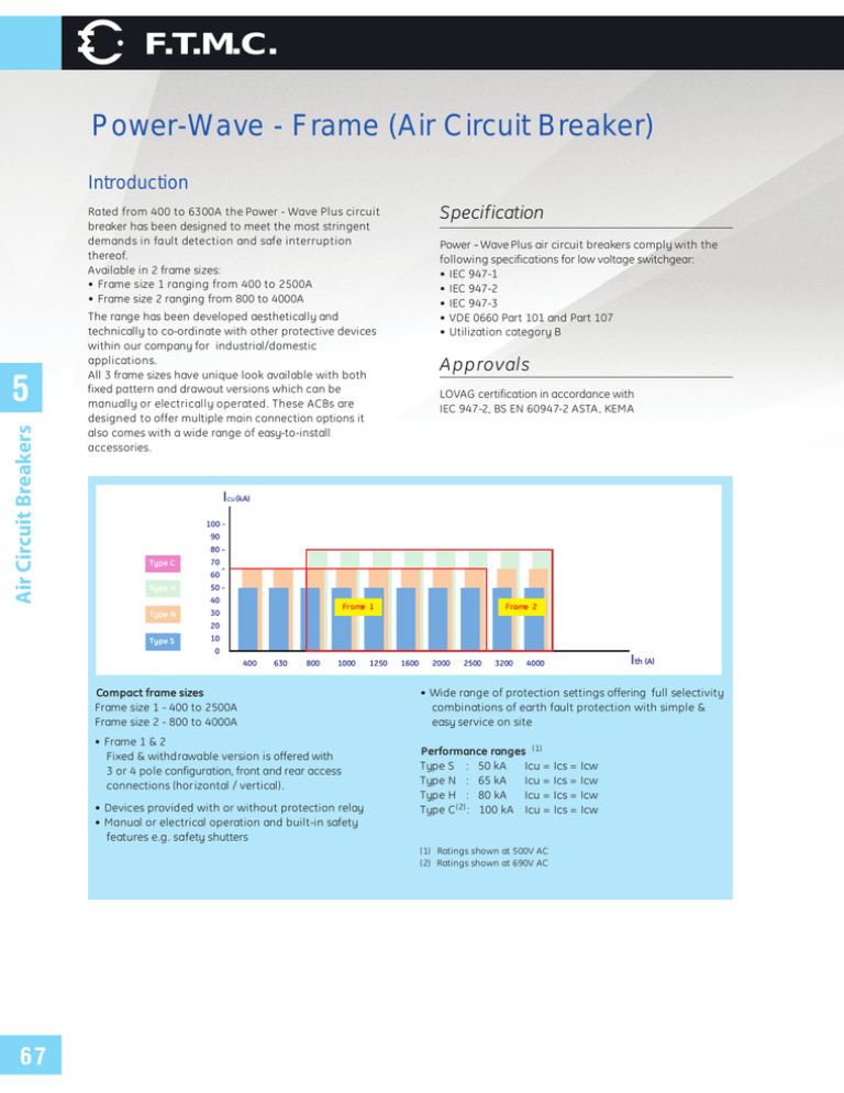
F.T.M.C. Power-Wave - Frame (Air Circuit Breaker) Introduction Specification Rated from 400 to 6300A the Power - Wave Plus circuit breaker has been designed to meet the most stringent demands in fault detection and safe interruption thereof. Available in 2 frame sizes: • Frame size 1 ranging from 400 to 2500A • Frame size 2 ranging from 800 to 4000A Air Circuit Breakers 5 Power - Wave Pl u s ai r ci rcu i t b reakers co mp l y wi t h t h e fo l l o wi n g specifications for low voltage switchgear: • IEC 947-1 • IEC 947-2 • IEC 947-3 • VDE 0660 Part 101 and Part 107 • Utilization category B The range has been developed aesthetically and technically to co-ordinate with other protective devices within our company for industrial/domestic applications. All 3 frame sizes have unique look available with both fixed pattern and drawout versions which can be manually or electrically operated. These ACBs are designed to offer multiple main connection options it also comes with a wide range of easy-to-install accessories. Approvals LOVAG certification in accordance with IEC 947-2, BS EN 60947-2 ASTA , KEMA ICU (kA) 100 90 80 Type C 70 60 Type H - 50 40 Type N Frame 1 30 Frame 2 20 Type S 10 0 400 630 800 1000 Compact frame sizes Frame size 1 - 400 to 2500A Frame size 2 - 800 to 4000A • Frame 1 & 2 Fixed & withdrawable version is offered with 3 or 4 pole configuration, front and rear access connections (hor izontal / vertical) . • Devices provided with or without protection relay • Manual or electrical operation and built-in safety features e.g. safety shutters 1250 1600 2000 2500 3200 • Wide range of protection settings offering full selectivity combinations of earth fault protection with simple & easy service on site Performance ranges (1) Type S : 50 kA Icu = Type N : 65 kA Icu = Type H : 80 kA Icu = Type C (2) : 100 kA Icu = (1) Ratings shown at 500V AC (2) Ratings shown at 690V AC 67 Ith (A) 4000 Ics = Ics = Ics = Ics = Icw Icw Icw Icw F.T.M.C. Power-Wave Installation Fixed pattern Power-WAVE Plus can be fastened into any suitable switchboard or cubicle arrangement using four M8 bolts. Clearance is only required above the unit for the removal and inspection of the arc chutes (see dimensional drawings for mounting details and recommended clearance distances). An earthing point is provided on either side of the circuit breaker. Power supply All stated short-circuit ratings are certified with incoming supply connection made to either upper or lower terminals. A l l P ower- WAVE Pl u s fixed p at t ern ai r ci rcu i t b reakers incorporate a stored energy mechanism. The spring can be charged either manually or electrically via a motor operator that is automatically activated after the closing operation. IP43 front panel and door escutcheon seals are standard features with IP20 protected secondary isolating contacts. For enhanced protection, an optional IP54 door panel is also available. 3 4 5 3 6 2 7 8 9 10 1 11 5 Air Circuit Breakers Fixed Pattern Circuit Breaker Frame 1 & 2 12 • • • • • • • • • • • • • • Trip-free operating mechanism Positive ’ON/OFF’ main contact indication Mechanical/electrical anti-pumping device Charging spring status indication Ergonomic manual spring charging handle Field-mountable range of accessories Auxiliary switches 5 NO and 3 NC, potential free 10A 250V (standard) Mechanical trip alarm switch (1 NO/NC) (optional) Padlockable push-button cover (for mechanical and electrical lock) Mechanical cable interlocking (optional) Termination: rear, horizontal or front access (optional) Electrical clearances according to IEC 947-2 Front access of secondary terminals for simple connection Maintainable arcing contacts are offered as a standard feature. 1. 2. 3. 4. 5. 6. 7. 8. 9. 10. 11. 12. Motorised spring charging unit (optional) FTCCM - protection relay (optional) Secondary contacts Shunt trip (optional) Closing coil (optional) Undervoltage release (optional) Manual charging handle ON/OFF push-buttons Push-button padlockable covers Positive contact indication Charging spring status indication Mounting plate 68 F.T.M.C. Power-Wave Withdrawable Pattern Circuit Breaker Frame 1 & 2 Power supply All stated short-circuit ratings are certified with incoming suppl y connection made to either upper or lower terminals. Air Circuit Breakers 5 Pre-mounted into a self-contained ’cassette’, this versatile circuit breaker can be inserted or withdrawn via sliding rails using a racking drive mechanism controlled by a racking handle. It provides three set positions: Disconnected / Test / Connected. Any attempt to withdraw the unit whilst in service will automatically trip the breaker, either by the racking position safety mechanism or by the insertion of the racking handle. It can be racked to the disconnected position with the cubicle door closed or open. Installation Circuit breakers are delivered pre-mounted in the cassette (standard) arrangements allow mounting onto any Versatile switchboard or cubicle using four M8 bolts (see dimensional drawings for mounting details and recommended clearance distances) Earthing point situated on the right hand side of cassette (front view) 4 3 2 1 5 10 9 8 • • • • • • • • • • • 69 Insulated shutters to isolate the main contact zone Front access padlocking for safety shutters Secure padlocking in the "Disconnect" position Clearly visibl e operational position indication Carriage position switch (o ptional) Termination: Flat copper palms (standard) with captive M10 fixing nuts Rear terminal adaptors for horizontal/vertical connection (o ptional) Front access connection (optional) Automatic disconnect of secondary circuits Lifting lugs for ease of removing the circuit breaker from the cassette (Power-Wave Plus handling truck required) Front access of secondary terminals for simple connection 1. 2. 3. 4. 5. 6. 7. 8. 9. 10. 11. 7 6 Carriage position switch (optional) Slide rails Insulated safety shutter Secondary terminals 2 or 3 way interlock mechanism (optio nal) Racking handle (storage) Padlocking for safety shutters Insertion hole for racking handle Padlocking in the DISCONNECTED position Operational positio n indication Key interlock (optio nal) * * Feature not visible in picture F.T.M.C. Power-Wave Characteristics Performance Data Symbol In Ue Ui Uimp Icu Ics Icw Icw W W Units A 400 630 800 1000 1250 20000 10000 5000 690 1000 8000 3&4 100% S N 1 1 20000 10000 5000 690 1000 8000 3&4 100% S N 1 1 20000 10000 5000 690 1000 8000 3&4 100% 20000 10000 5000 690 1000 8000 3&4 100% 20000 10000 5000 690 1000 8000 3&4 100% S 1 N 1 S 1 N 1 S 1 N 1 50 50 50 50 40 65 65 65 50 40 50 50 50 50 40 65 65 65 50 40 50 50 50 50 40 65 65 65 50 40 50 50 50 50 40 65 65 65 50 40 50 50 50 50 40 65 65 65 50 40 50 50 50 50 40 65 65 65 50 40 50 50 50 50 40 65 65 65 50 40 50 50 50 50 40 65 65 65 50 40 50 50 50 50 40 65 65 65 50 40 50 50 50 50 40 65 65 65 50 40 kA (rms) 50 kA (rms) 40 kA (peak) 143 143 143 84 Watt 16 Watt 33 65 50 143 143 105 84 11 22 50 40 143 143 143 84 39 75 65 50 143 143 105 84 27 53 50 40 143 143 143 84 63 127 65 50 143 143 105 84 43 86 50 40 143 143 105 84 106 211 65 50 143 143 105 84 68 135 50 40 143 143 143 84 175 351 65 50 143 143 105 84 105 211 V V V kA (rms) kA (rms) Temperature deratings Free A i r (1) The Power-Wave Plus ACBs may operate at higher ambient temperatures than 40°C in certain installation conditi ons. In this case the current rating in Amperes should be reduced as indicated below. Ambient temp. around the breaker Current rating (A) above 40°C Rated current (A ) 800 1000 1250 1600 2000 2500 3200 4000 50°C 800 1000 1250 1600 2000 2450 3200 3727 60°C 800 1000 1250 1445 2000 2232 3200 3367 Th e figures specified apply to withdrawable ACBs' with flat face vertical copper connections. (1) Protection degree IP00. For use in enclosures with interior temperatures of 40°C to 60°C the relevant IP values can be applied. 5 Air Circuit Breakers Characteristics Rated current (40°C) Endurance(n° of operating cycles) Mechanical (with maintenance) Mechanical (without maintenance) Electrical ( at rated current) Rated service voltage (50/60 Hz) Rated insulationvoltage Rated impulse withstandvoltage Number of poles Rating of 4th pole ACB type Frame size Rated ultimate short-circuit Breaking capacity 220V 415V 500V 600V 690V Rated service short-circuit Breaking capacity 220V 415V 500V 600V 690V Rated short time withstandcurrent 1 second 3 seconds Rated short-circuit 415V making capacity 500V 600V 690V Power dissipation at In breaker) Power dissipation at In (withdrawable) Rated short-circuit capacity In accordance with IEC 947-2 at 415V Breaker range S N Rating (A) Type 400 to 4000 Fixed or withdrawable 400 to 4000 Fixed or withdrawable Icu Ics Icw 1 sec 50kA 500 ms 50kA 50kA 65kA - 65kA 65kA - Recommended minimum copper size In accordance with IEC 947-2 Rating (A) Copper / phase 400 630 800 1000 1250 1600 2000 2500 3200 4000 2 x 50 x 5 2 x 50 x 5 2 x 50 x 5 2 x 60 x 5 2 x 50 x 10 2 x 50 x 10 3 x 50 x 10 4 x 50 x 10 4 x 100 x 10 4 x 100 x 10 + 1 x 100 x 5 70 F.T.M.C. Power-Wave Air Circuit Breakers 5 1600 2000 2500 3200 4000 20000 10000 5000 690 1000 8000 3&4 100% 20000 10000 5000 690 1000 8000 3&4 100% 20000 10000 5000 690 1000 8000 3&4 100% 20000 10000 5000 690 1000 8000 3&4 100% 20000 10000 5000 690 1000 8000 3&4 100% S 1 N 1 S 1/2 N 1/2 S 1/2 N 1/2 S 2 N 2 S 2 N 2 50 50 50 50 40 65 65 65 50 40 50 50 50 50 40 65 65 65 50 40 50 50 50 50 40 65 65 65 50 40 50 50 50 50 40 65 65 65 50 40 50 50 50 50 40 65 65 65 50 40 50 50 50 50 40 65 65 65 50 40 50 50 50 50 40 65 65 65 50 40 50 50 50 50 40 65 65 65 50 40 50 50 50 50 40 65 65 65 50 40 50 50 50 50 40 65 65 65 50 40 50 40 143 143 143 84 287 574 65 50 143 143 105 84 196 392 50 40 143 143 143 84 224 490 65 50 143 143 105 84 224 490 50 40 143 143 143 84 224 490 65 50 143 143 105 84 224 490 50 40 143 143 143 84 418 888 65 50 143 143 105 84 418 888 50 40 143 143 143 84 571 1224 65 50 143 143 105 84 571 1224 Dimensions (mm) Frame size 1 Rating (A) Poles Version (1) Height (2) Length (3) Depth (4) 400 to 2500 3 W F W F W F W F W F W F 440 430 440 430 440 430 440 430 440 430 440 430 329 329 429 429 419 419 549 549 419 419 549 549 390 328 390 328 392 328 392 328 482 328 482 328 4 2 800 to 3200 3 4 2 4000 3 4 71 (1) Version W = Withdrawable F = Fixed (2) Height (H) is from mounting surface to highest part of the ACB (3) Length (L ) is distance between widest part of the breaker (4) Depth (D ) is from the cubicle door to the rear moulding F.T.M.C. Power-Wave Weights (kg) N range Frame 3 Pole 4 Pole 3 Pole 4 Pole 1 1 2 2 36 43 53 53 44 54 68 68 39 43 53 53 49 54 68 68 Frame 3 Pole 4 Pole 3 Pole 4 Pole 400 to 1600A 2000 to 2500A 800 to 3200A 4000A 1 1 2 2 63 72 90 111 77 90 117 144 68 72 90 111 84 90 117 144 Cassette only Frame 3 Pole 4 Pole 3 Pole 4 Pole 400 to 1600A 2000 to 2500A 800 to 3200A 4000A 1 1 2 2 27 29 37 58 33 36 49 76 29 29 37 58 36 36 49 76 400 to 1600A 2000 to 2500A 800 to 3200A 4000A Withdrawable ACB 5 Air Circuit Breakers S range Fixed pattern ACB 72 F.T.M.C. Power-Wave Air Circuit Breaker Draw Out - 50, 65 kA Air Circuit Breaker manual and electrical operated Drow out pattern : breaker and cassette with at copper terminal, rear connected including 5 NO and 3 NC auxiliary switch Air Circuit Breakers 5 73 Cat. No. 50 kA Ref. No. Cat. No. 65 kA Ref. No. FTCPWS31W04-A F101274 FTCPWN31W04-A F102084 FTCPWS4L1W04-A F101275 FTCPWN4L1W04-A F102085 LEFT 4 FTCPWS4R1W04-A F101276 FTCPWN4R1W04-A F102086 RIGHT 4 FTCPWS31W06-A F101277 FTCPWN31W06-A F102087 FTCPWS4L1W06-A F101278 FTCPWN4L1W06-A F102088 LEFT 4 FTCPWS4R1W06-A F101279 FTCPWN4R1W06-A F102089 RIGHT 4 FTCPWS31W08-A F101280 FTCPWN31W08-A F102090 FTCPWS4L1W08-A F101281 FTCPWN4L1W08-A F102091 LEFT 4 FTCPWS4R1W08-A F101282 FTCPWN4R1W08-A F102092 RIGHT 4 FTCPWS31W10-A F101283 FTCPWN31W10-A F102093 FTCPWS4L1W10-A F101284 FTCPWN4L1W10-A F102094 FTCPWS4R1W10-A F101285 FTCPWN4R1W10-A F102095 FTCPWS31W12-A F101286 FTCPWN31W12-A F102096 FTCPWS4L1W12-A F101287 FTCPWN4L1W12-A F102097 LEFT 4 FTCPWS4R1W12-A F101288 FTCPWN4R1W12-A F102098 RIGHT 4 FTCPWS31W16-A F101289 FTCPWN31W16-A F102099 FTCPWS4L1W16-A F101290 FTCPWN4L1W16-A F102100 LEFT 4 FTCPWS4R1W16-A F101291 FTCPWN4R1W16-A F102101 RIGHT 4 FTCPWS31W20-A F101292 FTCPWN31W20-A F102102 FTCPWS4L1W20-A F101293 FTCPWN4L1W20-A F102103 LEFT 4 FTCPWS4R1W20-A F101294 FTCPWN4R1W20-A F102104 RIGHT 4 FTCPWS31W25-A F101295 FTCPWN31W25-A F102105 FTCPWS4L1W25-A F101296 FTCPWN4L1W25-A F102106 FTCPWS4R1W25-A F101297 FTCPWN4R1W25-A F102107 FTCPWS32W20-A F101298 FTCPWN32W20-A F102108 FTCPWS4L2W20-A F101299 FTCPWN4L2W20-A F102109 LEFT 4 FTCPWS4R2W20-A F101300 FTCPWN4R2W20-A F102110 RIGHT 4 FTCPWS32W25-A F101301 FTCPWN32W25-A F102111 FTCPWS4L2W25-A F101302 FTCPWN4L2W25-A F102112 LEFT 4 FTCPWS4R2W25-A F101303 FTCPWN4R2W25-A F102113 RIGHT 4 FTCPWS32W32-A F101304 FTCPWN32W32-A F102114 FTCPWS4L2W32-A F101305 FTCPWN4L2W32-A F102115 LEFT 4 FTCPWS4R2W32-A F101306 FTCPWN4R2W32-A F102116 RIGHT 4 FTCPWS32W40-A F101307 FTCPWN32W40-A F102117 FTCPWS4L2W40-A F101308 FTCPWN4L2W40-A F102118 LEFT 4 FTCPWS4R2W40-A F101309 FTCPWN4R2W40-A F102119 RIGHT 4 Frame 1 1 1 1 1 1 1 1 2 2 2 2 Rating (A) Position of the 400 Poles 3 3 630 3 800 3 1000 LEFT 4 RIGHT 4 3 1250 3 1600 3 2000 3 2500 LEFT 4 RIGHT 4 3 2000 3 2500 3 3200 3 4000 F.T.M.C. Power-Wave Air Circuit Breaker Fixed 50 , 65 kA Air Circuit Breaker manual and electrical operated Fixed pattern : breaker with rear horizontal terminal including 5 NO and 3 NC auxiliary switch Cat. No. 65 kA Ref. No. Frame FTCPWS31F04-A F101310 FTCPWN31F04-A F102120 1 FTCPWS4L1F04-A F101311 FTCPWN4L1F04-A F102121 LEFT 4 FTCPWS4R1F04-A F101312 FTCPWN4R1F04-A F102122 RIGHT 4 FTCPWS31F06-A F101313 FTCPWN31F06-A F102123 LEFT 4 RIGHT 4 FTCPWS4L1F06-A F101314 FTCPWN4L1F06-A F102124 FTCPWS4R1F06-A F101315 FTCPWN4R1F06-A F102125 FTCPWS31F08-A F101316 FTCPWN31F08-A F102126 FTCPWSS4L1F08-A F101317 FTCPWN4L1F08-A F102127 1 1 Rating (A) Position of the 400 Poles 3 3 630 3 800 LEFT 4 RIGHT 4 FTCPWS4R1F08-A F101318 FTCPWN4R1F08-A F102128 FTCPWS31F10-A F101319 FTCPWN31F10-A F102129 FTCPWS4L1F10-A F101320 FTCPWN4L1F10-A F102130 LEFT 4 FTCPWS4R1F10-A F101321 FTCPWN4R1F10-A F102131 RIGHT 4 1 3 1000 FTCPWS31F12-A F101322 FTCPWN31F12-A F102132 FTCPWS4L1F12-A F101323 FTCPWN4L1F12-A F102133 LEFT 4 FTCPWS4R1F12-A F101324 FTCPWN4R1F12-A F102134 RIGHT 4 FTCPWS31F16-A F101325 FTCPWN31F16-A F102135 LEFT 4 RIGHT 4 FTCPWS4L1F16-A F101326 FTCPWN4L1F16-A F102136 FTCPWS4R1F16-A F101327 FTCPWN4R1F16-A F102137 FTCPWS31F20-A F101328 FTCPWN31F20-A F102138 FTCPWS4L1F20-A F101329 FTCPWN4L1F20-A F102139 FTCPWS4R1F20-A F101330 FTCPWN4R1F20-A F102140 FTCPWS31F25-A F101331 FTCPWN31F25-A F102141 FTCPWS4L1F25-A F101332 FTCPWN4L1F25-A F102142 FTCPWS4R1F25-A F101333 FTCPWN4R1F25-A F102143 1 1 1 1 3 1250 3 1600 3 2000 LEFT 4 RIGHT 4 3 2500 LEFT 4 RIGHT 4 FTCPWS32F20-A F101334 FTCPWN32F20-A F102144 FTCPWS4L2F20-A F101335 FTCPWN4L2F20-A F102145 LEFT 4 FTCPWS4R2F20-A F101336 FTCPWN4R2F20-A F102146 RIGHT 4 FTCPWS32F25-A F101337 FTCPWN32F25-A F102147 LEFT 4 RIGHT 4 2 2 3 2000 3 2500 FTCPWS4L2F25-A F101338 FTCPWN4L2F25-A F102148 FTCPWS4R2F25-A F101339 FTCPWN4R2F25-A F102149 FTCPWS32F32-A F101340 FTCPWN32F32-A F102150 FTCPWS4L2F32-A F101341 FTCPWN4L2F32-A F102151 LEFT 4 FTCPWN4R2F32-A F102152 RIGHT 4 FTCPWS4R2F32-A F101342 2 3 3200 FTCPWS32F40-A F101343 FTCPWN32F40-A F102153 FTCPWS4L2F40-A F101344 FTCPWN4L2F40-A F102154 LEFT 4 FTCPWS4R2F40-A F101345 FTCPWN4R2F40-A F102155 RIGHT 4 2 5 Air Circuit Breakers Ref. No. Cat. No. 50 kA 3 4000 74


