Technical Documentation
advertisement
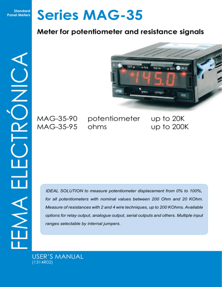
Series MAG-35 Standard Panel Meters FEMA ELECTRÓNICA Meter for potentiometer and resistance signals MAG-35-90 MAG-35-95 potentiometer up to 20K ohms up to 200K IDEAL SOLUTION to measure potentiometer displacement from 0% to 100%, for all potentiometers with nominal values between 200 Ohm and 20 KOhm. Measure of resistances with 2 and 4 wire techniques, up to 200 KOhms. Available options for relay output, analogue output, serial outputs and others. Multiple input ranges selectable by internal jumpers. USER’S Manual (1314r02) User’s Manual MAG-35-90 and 95 Models 90 and 95 Models for potentiometers and resistances Panel meters to measure the position of a potentiometer with nominal value between 200 Ohm and 20 KOhm. Measured range from 0% to 100% of the potentiometer, with display scalable in engineering units. Model to measure resistances in 2 and 4 wire techniques, from 200 Ohms up to 200 KOhms, with direct display of the resistance value in Ohms or KOhms. Additional options with relay outputs (1 or 2 relay), analogue outputs (in mA and Vdc), digital outputs in serial code (RS232 or RS485), parallel BCD code, display «Hold» function and power options in AC and DC. Order Reference Model MAG-35 - 90 -90 -95 Power - 0 Option 2 Option 1 - - -0 -1 -2 -3 -6 -8 -SP11 -SP21 -SDA -RS2 -RS4 Option 3 - -SAR -MPA2 Range - -HM 0/100% = 0/250 mm -0/100%=0/250 m -10/80%=-25.0/+150.0 mm - 0/20K=0/19.99 K -... Technical Data Options DISPLAYS Led 7 Segments Red Color DIGIT HEIGHT 14 mm (0.55’’) DISPLAY±1.8.8.8 POLARITY Automatic ± DECIMAL POINTS Jumper selectable INPUT CONFIGURATION A/D CONVERTER INTEGRATION TIME NUMBER OF READINGS WARM-UP TIME Bipolar Simple Dual slope 80 mSec. 3.12 per second 2 minutes ACCURACY0.15% ±1 digit (model 90) 0.5% ±1 digit (model 95) NMRR 50 dB THERMAL DRIFT 50 ppM TEMPCO ZERO 0.13% /ºC F.S. OVERRANGE UNDERRANGE +1999 flash -1999 flash WORKING TEMP. STORAGE TEMP. BURN-IN 0°C to +50°C -40°C to +80°C 48 hours HOUSING DIMENSIONS PANEL CUT-OUT WEIGHT CONNECTIONS DIN 43700 96 x 48 x 117 mm 44.5 x 92.5 mm 310 gr. Plug-in screw clamps CONSUMPTION 5.5 VA in AC 3.5 W in DC MAG-35 instruments can be supplied with different options for data output and control. Compatibility between them is indicated at the «Ordering Reference» section down on this page. Technical data and operating instructions for these options are indicated in a separate user’s manual. «SP11» «SP21» «SAR» «HM» «MPA2» «SDA» «RS2» «RS4» 1 Relay Output 2 Relay Output Analogue Output Hold of display Detection of «peak and drop» signals Parallel BCD Serial RS232 output Serial RS485 output Power MAG-35 instruments can be supplied with different power options, for different AC and DC power ranges. The instruments do not have internal protection fuse. The value and type of the recommended fuse for each power type is indicated below. Ref. «0» «1» «2» «3» «6» «8» Power 230 Vac 115 Vac 24 Vac 48 Vac 24 Vdc 48 Vdc 50/60 Hz 50/60 Hz 50/60 Hz 50/60 Hz (15/30 Vdc Isolated) (24/65 Vdc Isolated) FEMA ELECTRÓNICA - Page 2 Recommended Fuse 50 mA Time Lag 100 mA Time Lag 300 mA Time Lag 150 mA Time Lag 350 mA Fast Fuse 200 mA Fast Fuse User’s Manual MAG-35-90 and 95 MAG-35-90 MAG-35-95 for Potentiometers up to 20 KOhms for Resistances up to 200 KOhms Instrument to measure the position of a potentiometer with a range of 0% to 100% of the potentiometer. For all potentiometers with nominal values between 200 Ohm and 20 KOhm. Display scalable in engineering units (Kilos, mm, ...). Connection with 3 wires. Instrument to measure resistance signals up to 200 KOhms. Different signal ranges selectable by internal jumpers. Measures with 2 and 4 wires technique for compensation of the errors introduced by the ohm resistance of the wires. Direct display of the value in Ohms. READING SCALE SELECTION READING SCALE SELECTION Scale the reading to the desired value at full scale, by selecting the jumpers on the «MM» module, as shown on table below, and select jumpers «D» to light the decimal point (see figure 1 on page 4). Potentiometer «P2» allows manual adjustment of reading at full-scale. Potentiometers «SPAN» and «OFFSET» at the front of the instrument are for small «on-the-field» error corrections on the scaled display. Scale the desired measuring range, by selecting the jumpers on the «MM» module, as shown on table below, and select jumpers «D» to light the decimal point (see figure1 on page 4). Potentiometer «P2» allows manual adjustment of the reading at full-scale. Potentiometer «SPAN» at the front of the instrument is for small «on-the-field» manual error corrections on the scaled display. C B A P1 K L M N O P P2 SPAN ADJUST D C B A INTERNAL MODULE «MM» P1 ABCD P2 SPAN ADJUST INTERNAL MODULE «MM» Table 1 - Span display Table 2 - Offset display SPANJUMPER «MM» OFFSETJUMPER RANGE«MM» RANGEJUMPER JUMPER DISPLAY «MM» «D» 0 / 1000 K 0 / 500 P 200 KOhms D D1 1001 / 2000 --- 501 / 1000 --- 20 KOhms C L 1001 / 1999 N 2000 Ohms B 200 Ohms A 2001 / 4000 Note 1 .- The circuit to measure must be free of potential. OFFSETJUMPER TYPE«MM» Iref 199.9 K 0.01 mA D2 19.99 K 0.1 mA --- 1999 Ohms 1 mA D1 199.9 Ohms 10 mA Note 1 .- The circuit to measure must be free of potential. Note 2 .- to measure with 2 wire technique, short-circuit terminals «A-B» and «C-D» POSITIVE O NEGATIVE M CONNECTIONS Pot CONNECTIONS Iref (-) 0V (Common Signal C B A Res 2 1 10 9 Signal (+) Iref (+) +5 Vdc Hold (optional) D C B A 2 1 10 9 Hold (optional) - + Power - + Power (See label on the instrument) FRONT VIEW Signal (-) (See label on the instrument) FRONT VIEW SPAN OFFSET SPAN Light adjust of span OFFSET Light adjust of zero FEMA ELECTRÓNICA - Page 3 SPAN OFFSET SPAN Light adjust of span OFFSET Disabled User’s Manual MAG-35-90 and 95 Decimal point selection D1 D2 D3 D1D2D3 1 . XXX 1X . XX 1XX . X Mechanical dimensions (mm / inch.) ct io n bl an k MODULE «MM» 5 max (0,20’’) se 13 (0,51’’) 102 15 (0,60’’) Th is (4,02’’) 48 PANEL CUT-OUT 92.5 x 44.5 mm (1,89’’) (3.64’’ x 1.75’’) 96 (3,78’’) CE Declaration of conformity Manufacturer FEMA ELECTRÓNICA, S.A. Altimira 14 - Pol. Ind. Santiga E08210 - Barberà del Vallès BARCELONA - SPAIN www.fema.es - info@fema.es Series MAG-35, models 01, 02, 03, 04, 06, 07, 08, 10, 11, 12, 15, 16, 17, 20, 21, 22, 23, 24, 25, 26, 27, 32, 35, 36, 80, 90, 95 The manufacturer declares that the instruments indicated comply with the directives and rules indicated below. Directive of electromagnetic compatibility 2004/108/CEE Directive of low voltage 73/23/CEE Security rules 61010-1 Emission rules 50081-1 Immunity rules 50082-2 Barberà del Vallès October 2009 Daniel Juncà - Quality Manager FEMA ELECTRÓNICA - Page 4
