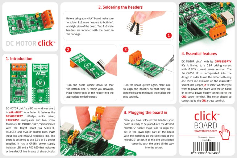
2. Soldering the headers
Before using your click™ board, make sure
to solder 1x8 male headers to both left
and right side of the board. Two 1x8 male
headers are included with the board in
the package.
DC MOTOR click
2
1
3
1. Introduction
Turn the board upside down so that
the bottom side is facing you upwards.
Place shorter pins of the header into the
appropriate soldering pads.
DC MOTOR click™ is a DC motor driver board
in mikroBUS™ form factor. It features the
DRV8833RTY H-Bridge motor driver,
74HC4053 multiplexer and two screw
terminals. DC MOTOR click™ communicates
with the target board via SELECT1,
SELECT2 and nSLEEP control lines, PWM
input line and nFAULT feedback line. The
board is designed to use 3.3V or 5V power
supplies. It has a GREEN power supply
indicator LED and a RED LED that indicates
active nFAULT line (in case of short-circuit).
Turn the board upward again. Make sure
to align the headers so that they are
perpendicular to the board, then solder the
pins carefully.
3. Plugging the board in
Once you have soldered the headers your
board is ready to be placed into the desired
mikroBUS™ socket. Make sure to align the
cut in the lower-right part of the board
with the markings on the silkscreen at the
mikroBUS™ socket. If all the pins are aligned
correctly, push the board all the way
into the socket.
4. Essential features
DC MOTOR click™ with its DRV8833RTY
IC’s is limited to a 0.9A driving current
with 0.22Ω current sense resistor. The
74HC4053 IC is incorporated into the
design in order to run the motor with only
one PWM line available on the mikroBUS™
socket. Use jumper J2 to select whether you
want to power the board with the on-board
or external power supply connected to the
CN2 screw terminal. The motor should be
connected to the CN1 screw terminal.
click
BOARD
www.mikroe.com
DC Motor click Manual
ver. 1.01
0 100000 025468
6. SMD Jumpers
R3
47K
VCC
VM
VCC
C1
C2
10uF
100nF
C3
VM
OUT2
R2
0.22
GND
C4
VINT
GND
VM
VCP
10nF
12
11
10
9
DRV8833RTY
PWM1
PWM0
GPIOB
SELECT1
GPIOA
1
2
3
4
5
6
7
8
C5
2.2uF
VCC
U2
2Y1
2Y0
3Y1
3Z
3Y0
E
VEE
GND
VDD
2Z
1Z
1Y1
1Y0
S1
S2
S3
R7
10K
16
15
PWM
14
13
12
11
10 SELECT2
9
FAULT
CN1
J2B
R1
2K2
POWER
LD2
74HC4053
VCC-EXT
OUT1
nFAULT
GPIOB
PWM1
VM
VCC
R5
0.22
AISEN
AOUT2
BOUT2
BISEN
Q1
BC856
220
5
6
7
8
MIKROBUS DEVICE CONN.
1
2
3
4
AOUT1
nSLEEP
AIN1
AIN2
PWM
nFAULT
PWM
INT
TX
RX
SCL
SDA
+5V
GND
BOUT1
nFAULT
BIN1
BIN2
AN
RST
CS
SCK
MISO
MOSI
+3.3V
GND
There is a single SMD jumper (zero-ohm
resistor) J1 which is used to select between
3.3V or 5V power supplies. By default, it’s
soldered in the 3.3V position.
VCC
R4
2K2
R6
VCC
U1
nSLEEP
SELECT1
SELECT2
nFAULT
100nF
74HC4053
VCC
VM
16
15
14
13
J1A
VCC
OUT1
nSLEEP
PWM0
GPIOA
5. DC MOTOR click™ Board Schematic
OUT2
OUT1
LD1
7. Code Examples
Once you have done all the necessary
preparations, it’s time to get your click™ board
up and running. We have provided examples
for mikroC™, mikroBasic™ and mikroPascal™
compilers on our Libstock website. Just
download them and you are ready to start.
SCREW TERMINAL
CN2
SCREW TERMINAL
.com
With two control lines SELECT1, SELECT2 and PWM input you can choose from the following driving options described in the table:
SELECT1
SELECT2
PWM
ROTATION
SPEED
BRAKE
DECAY
0
0
0-100%
Forward
MIN-MAX
@ 0% PWM
Fast
0
1
0-100%
Reverse
MIN-MAX
@ 0% PWM
Fast
1
0
0-100%
Reverse
MAX-MIN
@ 100% PWM
Slow
1
1
0-100%
Forward
MAX-MIN
@ 100% PWM
Slow
MikroElektronika assumes no responsibility or liability for any errors or inaccuracies that may appear in the present document.
Specification and information contained in the present schematic are subject to change at any time without notice. Copyright © 2014 MikroElektronika. All rights reserved.
8. Support
MikroElektronika offers Free Tech Support
(www.mikroe.com/support/) until the end
of the product’s lifetime, so if something
goes wrong, we’re ready and willing to help!


