GEN series
Features and Benefits
-
-
-
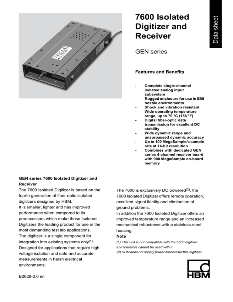
GEN series 7600 Isolated Digitizer and
Receiver
The 7600 Isolated Digitizer is based on the
fourth generation of fiber-optic isolated
digitizers designed by HBM.
It is smaller, lighter and has improved
performance when compared to its
predecessors which make these Isolated
Digitizers the leading product for use in the
most demanding test lab applications.
The digitizer is a single component for
integration into existing systems only(1).
Designed for applications that require high
voltage isolation and safe and accurate
measurements in harsh electrical
environments.
B2628-2.0 en
Complete single-channel
isolated analog input
subsystem
Rugged enclosure for use in EMI
hostile environments
Shock and vibration resistant
Wide operating temperature
range, up to 70 °C (158 °F)
Digital fiber-optic data
transmission for excellent DC
stability
Wide dynamic range and
unsurpassed dynamic accuracy
Up to 100 MegaSample/s sample
rate at 14-bit resolution
Combines with dedicated GEN
series 4-channel receiver board
with 900 MegaSample on-board
memory
The 7600 is exclusively DC powered(2), the
7600 Isolated Digitizer offers remote operation,
excellent signal fidelity and elimination of
ground problems.
In addition the 7600 Isolated Digitizer offers an
improved temperature range and an increased
mechanical robustness with a stainless-steel
housing.
Note
(1) This unit is not compatible with the 6600 digitizer
and therefore cannot be used with it.
(2) HBM does not supply power sources for this digitizer.
Data sheet
7600 Isolated
Digitizer and
Receiver
Front-end specifications (Transmitter)
Analog input section
Component
Unit Description
Value
Channels
Per front-end
1
Input type
Single-ended to isolated common (unbalanced differential) (1)
1
Coupling
AC / DC / GND / Reference
Connector
BNC
1
Ranges
Full Scale in 1, 2, 5 steps
± 20 mV to ± 100 V
Zero suppression
Automatic, equal to range
Impedance
1 MΩ (± 2 %) // 38 pF (± 5 %)
Bandwidth
Passband flatness
CMRR
@ -3 dB (wideband)
25 MHz
@ -3 dB (filtered)
10 MHz
Ranges: ± 0.1 dB over full temperature range
< 4 V, DC to 2.5 MHz
Ranges: ± 0.2 dB over full temperature range
≥ 4 V, DC to 2.5 MHz
@ 80 Hz (1)
100 dB
MSE
0.1 % FS ± 50 μV RTI(2)
Offset error
0.1 % FS ± 50 μV RTI(2)
Noise (RMS)
0.05 % FS ± 0.1 mV RTI
Bias current
< 2 nA
Rise time
14 ns
Recovery time(3)
Overload
Anti-alias filter
HBM
To 10 % following a 200 % Full Scale input
≤ 10 ns
To 0.1 % following a 200 % Full Scale input
≤ 50 ns
Protected for ranges ≥ ± 2 V
125 Vpeak protected for ranges < ± 2 V
250 Vpeak
Transient (impulse spark-over voltage at 1 kV/μs)
800 Vpeak
Low-pass at 10 MHz
6th order Bessel
Figure 1.1: Bandwidth plot in 0.4 V range
Figure 1.2: Bandwidth plot in 0.4 V range (detail)
Figure 1.3: Bandwidth plot in 4 V range
Figure 1.4: Bandwidth plot in 4 V range (detail)
2
B2628-2.0 en
Figure 1.5: Bandwidth plot in 40 V
Figure 1.6: Bandwidth plot in 40 V range (detail)
Testing and control section
Component
Unit Description
Value
Power On/Off (transmitter)
Controlled by Perception
Reference signal accuracy
Switched on via “Coupling” in Perception
Control Out
Digitizer section
Component
Conversion
Square wave
504 Hz +/- 1.8 V and +/- 0.09 V
Amplitude
+/- 0.5 %
Frequency
+/- 2 %
Switched on via "Control-Out" in Perception
Open collector output, sink-current
< 50 mA
Maximum open voltage; remotely controlled (open/closed) from
Perception software to control e.g. external power supply
12 V
Unit Description
Value
A-to-D Converter per channel Synchronous sampling between
channels
Single
Conversion rate
100 MS/s
Resolution
14 bit (0.006 %)
In enhanced mode (4)
16 bit
Aperture jitter
Fiber-optic link
Component
200 fs
Unit Description
Value
Light source
Class 1 laser product
1
Connector
LC Duplex
1
Transfer rate
2 Gbit/s
Wavelength
1310 nm
Cable type
Single mode
9/125 µm
Dynamic range
+ 9 dB
Isolation
1015 Ω/meter
Cable length
See Accesories
Maximum length(5)
Typical with standard off-the-shelf cable
4 km
Maximum with low-loss fiber optic cable
12 km
DC Power
Component
Supply
Note: Power sources not
available form HBM
B2628-2.0 en
Unit Description
Value
Normal
12 V DC
Minimum
11 V DC
Maximum
15 V DC
3
HBM
DC Power
Component
Warnings
Overheat
Overheat protection
Connector
Unit Description
Value
Maximum operating current
0.6 A
Maximum in sleep mode
80 mA
Isolation
SELV (6)
Low voltage warning
10.4 V
Automatic shut down
9.2 V
Red LED at receiver front panel indicates a transmitter internal
temperature
90 °C
(Externally)
(approx. 70 °C)
Transmitter shutdown
Automatic restart trial every 5 minutes after shutdown
95 °C
(Externally)
(approx. 75 °C)
Lemo
FGG.1B.303
Physical and environmental specifications
Component
Unit Description
Value
Dimensions
122.4 mm (4.82")
Width
Depth
237.0 mm (9.33")
Height
45.6 mm (1.79")
Figure 1.7: Isolated Digitizer 7600 Dimensions
Physical and environmental specifications
Component
Unit Description
Value
Weight
Maximum
1.3 kg
Shielding
Stainless Steel housing
(304)
Operating temp.
Normal operating temperatures
-10 °C to +70 °C (14 °F to
158 °F)
Humidity
Relative humidity (non-condensing)
0 % - 80 %
Altitude
Maximum operational altitude
2000 m (6100 ft)
Shock
acc. MIL-PRF-28800F Class 1,
Non-operational Shock test
30 g halfsine, 11 ms
Transit drop test: height
460 mm
Non-operational acceleration test
23 grms, 10 – 1500 Hz
All three axes for
30 seconds per axis
IP Rating
IP20
Vibration
Protection
Notes
(1)
Using an 'ideal' isolated power supply.
(2)
MSE and Offset error over the full temperature range will be 1 % of Full Scale.
(3)
Measured with a 1 kHz square wave signal at an input range of 1 V and no filter (wideband).
HBM
4
B2628-2.0 en
(4)
For sample rates ≤ 10 MHz and with digital filter ON.
(5)
Without additional connectors or patch boards.
(6)
SELV; safety extra-low voltage. In appliance standards (EN 60335)
All specifications are typical @ 25 °C (77 °F) unless otherwise stated and subject to change without notice in order
to improve design- and/or performance characteristics.
Consult www.hbm.com/highspeed for more information.
Receiver specifications
Fiber-optic link
Component
Unit Description
Value
Light source
Class 1 laser product
1
Connector
LC Duplex
1
Transfer rate
2 Gbit/s
Wavelength
1310 nm
Filtering
Component
Unit Description
Digital filters
Sample rate fs = 100 MS/s
No filter
Sample rate fs < 100 MS/s, User selectable in range (see value)
5 MHz to 50 kHz (in 12 steps)
Unit Description
Value
Monitor output
Component
Value
Outputs
one BNC per channel on receiver front panel
Output level
Full Scale (± 0.5 %)
±5V
± 20 mA
Output current
Output load
Conversion
> 250 Ω
D-to-A Converter per channel
Single
Conversion rate
100 MS/s
Resolution
14 bit (0.006 %)
Output filter
6-pole Bessel
Delay (7)
Delay from input to output:
10 MHz @ – 3 dB
Minimum: (filter = wideband)
< 1 µs
Maximum: (filter = 50 kHz)
12 µs
Transient memory
Component
Unit Description
Value
Capacity
On-board, to be used by enabled channels
900 MS (1.8 GigaByte)
Triggering
Component
Unit Description
Value
Type
Dual-level trigger digital trigger detector per channel
Pre/post trigger
Pre- and post trigger segment can be zero samples up to full memory
length
Rate
Maximum
1 trigger/10 ms up to 100
triggers/s
Zero re-arm time
B2628-2.0 en
5
HBM
Triggering
Component
Unit Description
Value
Resolution
On each level
16 bit (0.0015 %)
Acquisition modes
Component
Unit Description
Recorder
For continuous acquisition
Scope
For repetitive phenomena
Transient
For intermittent events; single, dual or A-B-A timebase
Data Storage
Component
Unit Description
Recorder
Value
Spooled directly to hard disk of control PC. Unlimited file size or
duration.
Maximum transfer rate:
10 MS/s per channel
Scope
Store in transient memory
Transient
Store in transient memory; single or A-B-A timebase
Notes
(7)
With 1 meter of fiber optic cable.
All specifications are typical @ 25 °C (77 °F) unless otherwise stated and subject to change without notice in order
to improve design- and/or performance characteristics.
Consult www.hbm.com/highspeed for more information.
Ordering information
Component
Four channel receiver
Ordering information
Component
Single channel transmitters
Unit Description
Order Number
7600 Enhanced receiver card for Genesis system. Single Mode
FO transmission. Accepts only 7600 Isolated digitizers. Includes
900 MS transient memory
1-GN402-2
Unit Description
Order Number
7600 Enhanced isolated digitizer, 100 MS/s, Single Mode FO link,
requires 7600 receiver
1-GN114-2
Accessories (to be ordered separately)
Component
Unit Description
Fiber Optic Cables
KAB288
HBM
Length
Order Number
Standard Isobe7600 Cable Pair (Patch panel/Indoor use only) 7600
Standard Zipcord fiber optic Single Mode cable, 0,5 dB/km loss, LCLC connectors, Yellow
2m
1-KAB288-2
Diameter
2.4 x 4.8 mm (0.09" x 0.19")
10 m
1-KAB288-10
Weight
14 kg/km (9 lbs/1000 ft)
20 m
1-KAB288-20
Tension long term
529 N (119 LBS)
50 m
1-KAB288-50
Bend radius
30 mm (1.2")
100 m
1-KAB288-100
Operating temp
0 °C to +70 °C
6
B2628-2.0 en
Accessories (to be ordered separately)
Component
Unit Description
Color
Length
Order Number
Yellow
Figure 1.8: Standard Isobe7600 Cable Pair
Accessories (to be ordered separately)
Component
Unit Description
Fiber Optic Cables
Heavy duty
KAB289
Length
Order Number
7600 Indoor/Outdoor, heavy duty, fiber optic, Single Mode cable,
0,5 db/km loss, LC-LC connectors, Black
10 m
1-KAB289-10
Diameter
5.8 mm (0.23")
20 m
1-KAB289-20
Weight
32 kg/km (21.5 lbs/1000 ft)
50 m
1-KAB289-50
Crush resistance
2000 N/cm
100 m
1-KAB289-100
Tension long term
290 N (66 LBS)
150 m
1-KAB289-150
Bend radius
5.8 cm (2.3")
300 m
1-KAB289-300
Operating temp.
-46 °C to +85 °C
Color
Black
Figure 1.9: Heavy Duty Isobe7600 Cable
Hottinger Baldwin Messtechnik GmbH
Im Tiefen See 45 ∙ 64293 Darmstadt ∙ Germany
Tel. +49 6151 803-0 ∙ Fax: +49 6151 803-9100
E-mail: info@hbm.com ∙ www.hbm.com
measure and predict with confidence
B2628-2.0 en
©Hottinger Baldwin Messtechnik GmbH. All rights reserved.
All details describe our products in general form only.
They are not to be understood as express warranty and do
not constitute any liability whatsoever.

