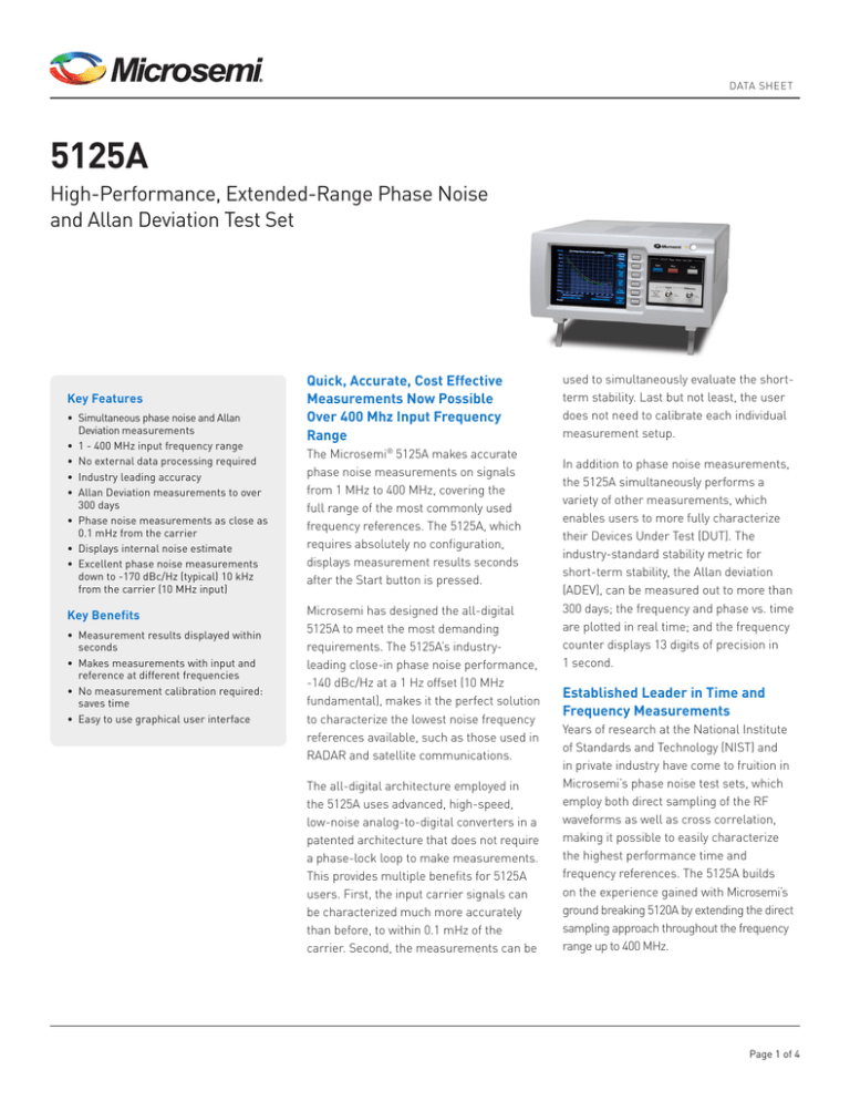
DATA SHEET
5125A
High-Performance, Extended-Range Phase Noise
and Allan Deviation Test Set
Key Features
• Simultaneous phase noise and Allan
Deviation measurements
• 1 - 400 MHz input frequency range
• No external data processing required
• Industry leading accuracy
• Allan Deviation measurements to over
300 days
• Phase noise measurements as close as
0.1 mHz from the carrier
• Displays internal noise estimate
• Excellent phase noise measurements
down to -170 dBc/Hz (typical) 10 kHz
from the carrier (10 MHz input)
Key Benefits
• Measurement results displayed within
seconds
• Makes measurements with input and
reference at different frequencies
• No measurement calibration required: saves time
• Easy to use graphical user interface
Quick, Accurate, Cost Effective
Measurements Now Possible
Over 400 Mhz Input Frequency
Range
The Microsemi® 5125A makes accurate
phase noise measurements on signals
from 1 MHz to 400 MHz, covering the
full range of the most commonly used
frequency references. The 5125A, which
requires absolutely no configuration,
displays measurement results seconds
after the Start button is pressed.
Microsemi has designed the all-digital
5125A to meet the most demanding
requirements. The 5125A’s industryleading close-in phase noise performance,
-140 dBc/Hz at a 1 Hz offset (10 MHz
fundamental), makes it the perfect solution
to characterize the lowest noise frequency
references available, such as those used in
RADAR and satellite communications.
The all-digital architecture employed in
the 5125A uses advanced, high-speed,
low-noise analog-to-digital converters in a
patented architecture that does not require
a phase-lock loop to make measurements.
This provides multiple benefits for 5125A
users. First, the input carrier signals can
be characterized much more accurately
than before, to within 0.1 mHz of the
carrier. Second, the measurements can be
used to simultaneously evaluate the shortterm stability. Last but not least, the user
does not need to calibrate each individual
measurement setup.
In addition to phase noise measurements,
the 5125A simultaneously performs a
variety of other measurements, which
enables users to more fully characterize
their Devices Under Test (DUT). The
industry-standard stability metric for
short-term stability, the Allan deviation
(ADEV), can be measured out to more than
300 days; the frequency and phase vs. time
are plotted in real time; and the frequency
counter displays 13 digits of precision in
1 second.
Established Leader in Time and
Frequency Measurements
Years of research at the National Institute
of Standards and Technology (NIST) and
in private industry have come to fruition in
Microsemi’s phase noise test sets, which
employ both direct sampling of the RF
waveforms as well as cross correlation,
making it possible to easily characterize
the highest performance time and
frequency references. The 5125A builds
on the experience gained with Microsemi’s
ground breaking 5120A by extending the direct
sampling approach throughout the frequency
range up to 400 MHz.
Page 1 of 4
DATA SHEET
5125A
Quickest Start-to-Finish
Measurements
Thanks to the 5125A’s innovative
internal architecture, it requires no user
configuration or calibration and thus
makes phase noise measurements in a
matter of seconds.
Extremely Wide Range
Measurement Capability
The 5125A supports a wide range
of phase noise and ADEV measurements.
By converting the DUT and Reference
signals to their digital representation
at the first stage, the all-digital design
in the 5125A has eliminated the need
for carrier suppression when making
measurements, enabling phase noise
measurements at smaller frequency
offsets than previously possible (to
below 0.1 mHz). This same technology
enables simultaneous long-term ADEV
measurements. Technical advances like
these provide the ability to characterize
high-performance sources better than
ever before.
Excellent Close-In Phase
Noise Floor
The 5125A’s built-in cross correlation
capability results in an extremely low
close-in phase noise floor. At 100 MHz,
measurements can be made down to -130
dBc/Hz (typical) at an offset of 1 Hz from
the carrier, making the 5125A an excellent
solution for the most demanding phase
noise measurement requirements.
..
.. 5125A Sample Display Capture – Phase Noise
.. Spurs are highlighted in red. The instrument’s real-time noise floor shown in gray, provides
.. the user with a way to estimate the 5125A’s internal noise bias on the current measurement.
.
Advanced Spur Detection
Easy to Use
The 5125A is equipped with sophisticated
algorithms that analyze spurious
signals in the spectrum simultaneous
with the phase noise measurement.
Internally generated spurs are detected
and suppressed. External spurs are
highlighted in red on the unit’s display,
as shown in the 5125A Sample Display
Capture – Phase Noise diagram above.
The power of each spur is calculated
without the need for a separate
measurement. The results are shown on
the phase noise plot as well as
in a separate table.
Microsemi has combined its extensive
knowledge in phase noise and ADEV
measurement techniques into a onebox solution with an intuitive, easyto-learn GUI. Since all configuration
and calibration are done by the 5125A,
extremely accurate measurements can
be made without a highly trained engineer
having to supervise the measurements.
Making measurements is as simple as
connecting the DUT and a reference and
pressing the Start button.
Page 2 of 4
DATA SHEET
5125A
No Longer Must the Reference and
DUT be at the Same Frequency
Unlike traditional measurement systems,
the 5125A does not require that the
frequency of the reference be the same as
the DUT. Two enablers for this advance are
that the 5125A synthesizes the two input
frequencies for conversion to baseband,
and the 5125A’s phase detector has infinite
range that doesn’t require the two inputs
to be phase locked. These advances allow
accurate measurements to be made on a
DUT at any frequency between 1-400 MHz,
with a single low noise reference.
Multiple Connectivity Options
Connecting a mouse and/or keyboard
directly to the 5125A’s USB ports makes
operating this instrument even easier.
When remote operation is required, the
user can connect to the 5125A’s Ethernet
port (over a standard 10/100 BaseT
network) to start/stop measurements,
gather raw phase data or measurement
results and print.
..
..
..
..
..
..
..
.
5125A Sample Display Capture – Allan Deviation
The instrument’s real-time self-calculated noise floor, which can be used to estimate the
5125A’s internal noise bias, is shown in gray. Allan Deviation measurements to over 300 days
are supported.
5125A Block Diagram
Page 3 of 4
DATA SHEET
5125A
Benefits Of An All-Digital Test Set
The 5125A combines sophisticated timing
technologies into a single, advanced
measurement instrument. As is shown
in the 5125A Block Diagram below, after
bandpass filtering to prevent undesired
aliasing, the DUT and reference
signals are converted to digital. This
allows the 5125A to make accurate
measurements without the need for an
external phaselock loop and to measure
both phase noise and Allan Deviation
simultaneously. The use of a ratiometric
phase measurement that depends on a
trigonometric phase detector eliminates
the need for user calibration.
Benefits of Cross-Correlation
The parallel measurement channels
in the 5125A Block Diagram illustrate
the unit’s use of cross correlation. After
making independent phase-difference
measurements, the 5125A computes
the cross spectrum using the discrete
Fourier transforms from the two
channels to estimate the noise of the
input devices while rejecting the noises
of the measurement sub-systems. This
enables the instrument noise to be well
below the noise floor of a single channel.
..
..
..
..
..
..
..
..
..
..
..
..
..
..
..
..
..
..
..
..
..
..
..
..
..
..
..
..
..
..
..
..
..
..
..
..
..
..
..
..
..
..
..
..
..
..
..
..
..
..
..
..
..
..
..
.
Specifications
PERFORMANCE
• Frequency range:
1-400 MHz (sinewave)
• Allan deviation: <3E-15 at 1 sec
(10-400 MHz, 0.5 Hz BW)
Phase Noise Specifications
• Measurement accuracy: ±1.0 dB
• Offset frequency range:0.1 mHz to 1 MHz
• System noise floor
(specifications): L(f) dBc/Hz
Offset Frequency 10 MHz Input Frequency
100 MHz 400 MHz
1 Hz -140 -120 -110
10 Hz -150 -130 -120
100 Hz -157 -140 -130
1 kHz -162 -150 -140
10 kHz -165 -160 -150
>100 kHz
-165 -162 -155
• System noise floor (typical): L(f) dBc/Hz
Offset Frequency 10 MHz Input Frequency
100 MHz 400 MHz
1 Hz -145 -130 -116
10 Hz -155 -140 -126
100 Hz -160 -150 -136
1 kHz -165 -160 -146
10 kHz -170 -170 -156
>100 kHz -170 -170 -162
ELECTRICAL SPECIFICATIONS
• Input signal level: 3-17 dBm
• Input impedance: 50Ω
• Input connectors: TNC (supplied with two
BNC adapters)
..
..
..
..
..
..
..
..
..
..
..
..
..
..
..
..
..
..
..
..
..
..
..
..
..
..
..
..
..
..
..
..
..
..
..
..
..
..
..
..
..
..
..
..
..
..
..
..
..
..
..
..
..
..
..
.
MECHANICAL & ENVIRONMENTAL SPECIFICATIONS
• Size: 34 cm x 17 cm x 44 cm (13" x 7" x17")
• Power: 100-240 VAC, 47-63 Hz
IEC 320 connector,
power switch.
• Operating temperature: 15°C to 45°C
• Storage temperature: –25°C to 55°C
OPTIONS
• Rack Mount Tray Kit (Option 001)
• Unlike the 5120A there is no internal reference
option
PRODUCT INCLUDES
5125A Test Set, 2 TNC-BNC adapters, manual (on CD) and
power cord.
One-year warranty.
FRONT PANEL
• Display: High-resolution 640x480
RGB LCD
• Buttons: 6 SoftKeys, Start, Stop,
Print, Power
• TNC (2x): Input, Reference (3-17 dBm)
• LED: Power
REAR PANEL
• USB: 2 each
• Network:
RJ-45 10/100BaseT
Ethernet
• Printers: Printers with internal
PostScript interpreters
only.
Microsemi Corporation (Nasdaq: MSCC) offers a comprehensive portfolio of semiconductor solutions for aerospace, defense and security;
enterprise and communications; and industrial and alternative energy markets. Products include high-performance, high-reliability analog
and RF devices, mixed signals and RF integrated circuits, customizable SoCs, FPGAs, and complete subsystems. Microsemi is headquartered
in Aliso Viejo, Calif. Learn more at
www.microsemi.com
Microsemi Corporate Headquarters
One Enterprise, Aliso Viejo, CA 92656 USA
Within the USA: +1 (949) 380-6100
Sales: +1 (949) 380-6136
Fax: +1 (949) 215-4996
©2014 Microsemi Corporation. All rights reserved. Microsemi and the Microsemi logo are trademarks of Microsemi Corporation. All other
trademarks and service marks are the property of their respective owners.
DS/5125A/060414 900 00482 000B


