Functional Safety Manual
advertisement
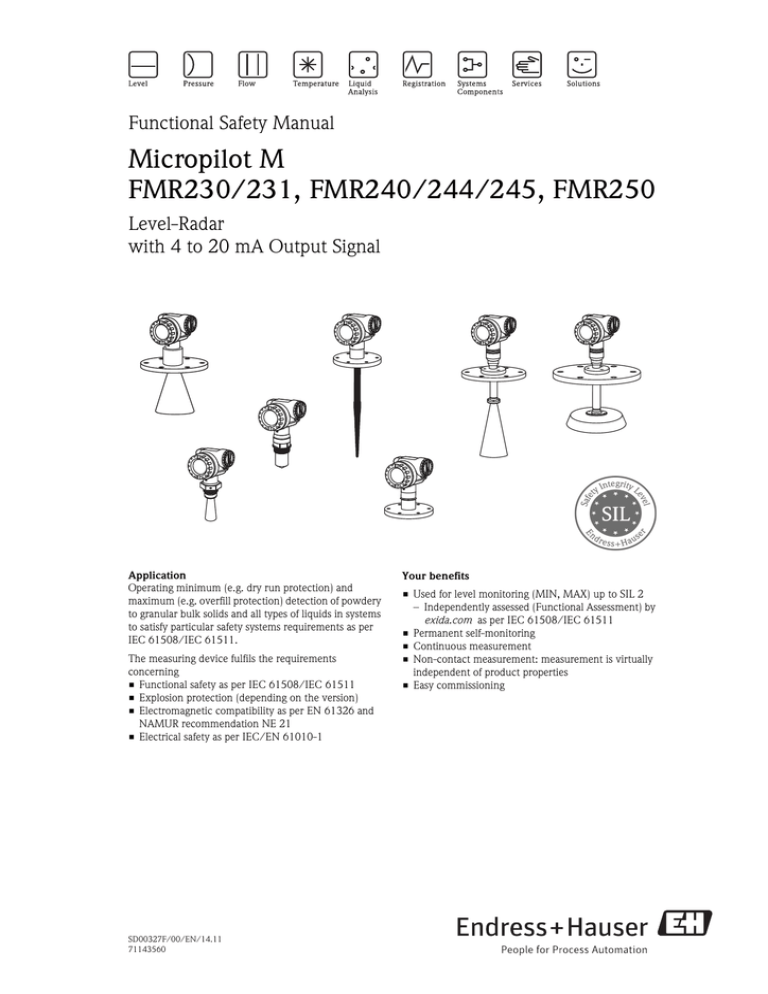
Functional Safety Manual Micropilot M FMR230/231, FMR240/244/245, FMR250 Level-Radar with 4 to 20 mA Output Signal Application Operating minimum (e.g. dry run protection) and maximum (e.g. overfill protection) detection of powdery to granular bulk solids and all types of liquids in systems to satisfy particular safety systems requirements as per IEC 61508/IEC 61511. The measuring device fulfils the requirements concerning • Functional safety as per IEC 61508/IEC 61511 • Explosion protection (depending on the version) • Electromagnetic compatibility as per EN 61326 and NAMUR recommendation NE 21 • Electrical safety as per IEC/EN 61010-1 SD00327F/00/EN/14.11 71143560 Your benefits • Used for level monitoring (MIN, MAX) up to SIL 2 – Independently assessed (Functional Assessment) by exida.com as per IEC 61508/IEC 61511 • Permanent self-monitoring • Continuous measurement • Non-contact measurement: measurement is virtually independent of product properties • Easy commissioning Micropilot M Table of contents SIL Declaration of Conformity . . . . . . . . . . . . . . . . . . . 3 Introduction. . . . . . . . . . . . . . . . . . . . . . . . . . . . . . . . . 4 Structure of the measuring system. . . . . . . . . . . . . . . . 4 System components . . . . . . . . . . . . . . . . . . . . . . . . . . . . . . . . . . . 4 Description of use as a protective system . . . . . . . . . . . . . . . . . . . . 5 Permitted device types . . . . . . . . . . . . . . . . . . . . . . . . . . . . . . . . . 5 Supplementary device documentation . . . . . . . . . . . . . . . . . . . . . . 7 Description of the safety requirements and boundary conditions . . . . . . . . . . . . . . . . . . . . . . . . . . 8 Safety function . . . . . . . . . . . . . . . . . . . . . . . . . . . . . . . . . . . . . . . 8 Restrictions for use in safety-related applications . . . . . . . . . . . . . . 8 Functional safety indicators . . . . . . . . . . . . . . . . . . . . . . . . . . . . . . 9 Behavior of device during operation and in case of error . . . . . . . 11 Installation . . . . . . . . . . . . . . . . . . . . . . . . . . . . . . . . . . . . . . . . . 11 Operation . . . . . . . . . . . . . . . . . . . . . . . . . . . . . . . . . . . . . . . . . . 11 Maintenance . . . . . . . . . . . . . . . . . . . . . . . . . . . . . . . . . . . . . . . 14 Proof-test . . . . . . . . . . . . . . . . . . . . . . . . . . . . . . . . . . 15 Proof-test . . . . . . . . . . . . . . . . . . . . . . . . . . . . . . . . . . . . . . . . . . 15 Process for proof-testing . . . . . . . . . . . . . . . . . . . . . . . . . . . . . . . 15 Repairs. . . . . . . . . . . . . . . . . . . . . . . . . . . . . . . . . . . . 16 Repairs . . . . . . . . . . . . . . . . . . . . . . . . . . . . . . . . . . . . . . . . . . . . 16 Appendix . . . . . . . . . . . . . . . . . . . . . . . . . . . . . . . . . . 17 Commissioning or proof test protocol . . . . . . . . . . . . . . . . . . . . . 17 Exida Management Summary . . . . . . . . . . . . . . . . . . 18 2 Endress+Hauser Micropilot M SIL Declaration of Conformity SIL_08006a_de Endress+Hauser 3 Micropilot M ! Introduction Note! General information on functional safety (SIL) is available at: www.de.endress.com/SIL (German) or www.endress.com/SIL (English) and in Competence Brochure CP002Z "Functional Safety in the Process Industry - Risk Reduction with Safety Instrumented Systems". Structure of the measuring system System components The measuring system's devices are displayed in the following diagram (example). FieldCare Commubox FXA191/195 FMR23x FMR24x FMR250 4...20 mA ENDRESS + HAUSER % – + E Logic Unit e.g. PLC, limit switch, ... Actuator Operating and display module VU331 SD00327en01 An analog signal (4 to 20 mA) in proportion to the level is generated in the transmitter. This is sent to a downstream logic unit (e.g. PLC, limit signal transmitter, etc.) where it is monitored to determine whether it is below or above a specified limit value. For fault monitoring, the logic unit must recognize both HI-alarms (≥ 21.0 mA) and LO-alarms (≤ 3.6 mA). 4 Endress+Hauser Micropilot M Description of use as a protective system The Micropilot M is a "downward-looking" measuring system that functions according to the ToF method (ToF = Time of Flight). The distance from the reference point (process connection of the measuring device) to the product surface is measured. Radar impulses are emitted by an antenna, reflected off the product surface and received again by the radar system. Typical measuring arrangement: Flange: reference point of measurement 20 mA 100 % 4 mA 0% SD00327en02 ! Permitted device types Note! Correct installation is a prerequisite for safe operation of the device. The details pertaining to functional safety in this manual relate to the device versions listed below and are valid as of the specified software and hardware version. Unless otherwise specified, all subsequent versions can also be used for safety instrumented systems. A modification process according to IEC 61508 is applied for device changes. Valid device versions for safety-related use: Micropilot M FMR230, FMR244 Feature Designation Version 010 Approval all 020 Antenna all 030 Antenna Seal; Temperature all 040 Process Connection all 050 Output; Operation A, B, K 060 Housing all 070 Cable Entry all 080 Additional Option all Valid software version: FMR230: as of 01.04.00; FMR244: as of 01.05.00 Valid hardware version (electronics): as of delivery date January 2010 Endress+Hauser 5 Micropilot M Micropilot M FMR231 Feature Designation Version 010 Approval all 020 Antenna; Inactive Length all 030 Process Connection all 040 Output; Operation A, B, K 050 Housing all 060 Cable Entry all 070 Gas-Tight Feed Through all 080 Additional Option all Valid software version: FMR231: as of 01.04.00 Valid hardware version (electronics): as of delivery date January 2010 Micropilot M FMR240, FMR250 Feature Designation Version 010 Approval all 020 Antenna all 030 Antenna Seal; Temperature all 040 Antenna Extension all 050 Process Connection all 060 Output; Operation A, B, K 070 Housing all 080 Cable Entry all 090 Additional Option all Valid software version: FMR240, FMR250: as of 01.05.00 Valid hardware version (electronics): as of delivery date January 2010 Micropilot M FMR245 Feature Designation Version 010 Approval all 020 Antenna all 030 Process Connection all 040 Output; Operation A, B, K 050 Housing all 060 Cable Entry all 070 Additional Option all Valid software version: FMR245: as of 01.05.00 Valid hardware version (electronics): as of delivery date January 2010 6 Endress+Hauser Micropilot M Supplementary device documentation Endress+Hauser Documentation Contents Comment Technical Information TI00345F/00 (FMR23x, FMR24x) TI00390F/00 (FMR250) – Technical data – Instructions on accessories – The documentation is available on the Internet. → www.de.endress.com. Operating Instructions (HART) BA00218F/00 (FMR230) BA00219F/00 (FMR231) BA00220F/00 (FMR240) BA00248F/00 (FMR244) BA00251F/00 (FMR245) BA00284F/00 (FMR250) – – – – – – – – – – Identification Installation Wiring Operation Commissioning Maintenance Accessories Troubleshooting Technical data Appendix – The documentation is supplied with the device. – The documentation is also available on the Internet. → www.de.endress.com. Operating Instructions (Device Functions) BA00221F/00 (FMR23x) BA00291F/00 (FMR24x, FMR250) – – – – – – – Instructions on use Micropilot M function menu Function groups ... ... Envelope curve Troubleshooting Function menu index – The documentation is available on the Internet. → www.de.endress.com. Safety instructions depending on the selected version "Approval" – Safety, installation and operating instructions for devices, which are suitable for use in potentially explosive atmospheres or as overfill protection (WHG, German Water Resources Act). Additional safety instructions (XA, XB, XC, ZE, ZD) are supplied with certified device versions. Please refer to the nameplate for the relevant safety instructions. 7 Micropilot M Description of the safety requirements and boundary conditions Safety function ! The mandatory settings and safety function data emanate from the descriptions from → ä 11. The measuring system's reaction time is ≤ 5 s. Note! MTTR is set at 8 hours. Safety-related signal: The Micropilot M's safety-related signal is the 4 to 20 mA analog output signal. All safety measures refer to this signal exclusively. The Micropilot M additionally communicates effectively via HART and contains all HART features with additional device information. The safety-related output signal is fed to a downstream logic unit, e.g. a programmable logic controller or a limit signal transmitter where it is monitored for the following: – Overshooting and/or undershooting a specified level limit. – The occurrence of a fault, e.g. error current (≤ 3.6 mA, ≥ 21.0 mA, interruption or short-circuit of the signal line). Restrictions for use in safetyrelated applications The measuring system must be used correctly for the specific application, taking into account the medium properties and ambient conditions. Carefully follow instructions pertaining to critical process situations and installation conditions from the Operating Instructions. The specifications from the Operating Instructions (→ ä 7, "Supplementary device documentation") must not be exceeded. The following restriction also applies to safety-related use: – The accuracy of the 4 to 20 mA safety-related output signal is ± 10%. 8 Endress+Hauser Micropilot M Functional safety indicators The following tables show specific indicators for functional safety. Characteristic as per IEC 61508 FMR23x with 4 to 20 mA output Safety functions MIN MAX SIL 2 HFT 0 Device type B Mode of operation Low demand mode SFF 67 % MTTR 8h Recommended time interval for proof-testing T1 λsd * 1 year 2 392 FIT 87 FIT 2 951 FIT 1125 FIT *2 541 FIT 846 FIT 916 FIT 710 FIT 2800 FIT 2768 FIT λsu * λdd 74 % λdu * 2 λtot * 3 PFDavg for T1 = 1 year *1 10-3 3,11 × 10⁻³ 4,75 × 10⁻³ 3,69 × 10⁻³ 4,01 × PFDavg for T1 = 1 year *5 MTBF *3 35 years System reaction time ≤5s *4 *1 PFDavg values for other T1-values see "Proof-test interval". 1 l • DU • T1 Calculation formula: PFDavg = 2 *2 According to Siemens SN29500. *3 According to Siemens SN29500, including faults outside the safety function. *4 Step response time as per DIN EN 61298-2. *5 Calculated, with MTTR = 24 h, lifetime (LT) = 10 years and proof test coverage (PTC) = 98 %, using the following formula: PFDavg = 1 • PTC • lDU • T1 + l DD • MTTR + 1 • (1 – PTC) • lDU • LT 2 2 PFDavg 1,00E-02 MIN MAX 5,00E-03 0,00E+00 0 1 2 years SD00327en03 Proof-test interval Endress+Hauser 9 Micropilot M Characteristic as per IEC 61508 FMR24x, FMR250 with 4...20 mA output Safety functions MIN MAX SIL 2 HFT 0 Device type B Mode of operation Low demand mode SFF 68 % 75 % MTTR 8h Recommended time interval for proof-testing T1 λsd * 1 year 2 356 FIT 99 FIT *2 1031 FIT 1207 FIT λdd * 621 FIT 878 FIT 903 FIT 697 FIT λsu 2 λdu * 2 λtot *3 2911 FIT 1 2881 FIT PFDavg for T1 = 1 year * 3,96 × 10 -3 3,05 × 10⁻³ PFDavg for T1 = 1 year *5 4,68 × 10⁻³ 3,62 × 10⁻³ MTBF *3 35 years System reaction time ≤5s *4 *1 PFDavg values for other T1-values see "Proof-test interval". 1 l • DU • T1 Calculation formula: PFDavg = 2 *2 According to Siemens SN29500. *3 According to Siemens SN29500, including faults outside the safety function. *4 Step response time as per DIN EN 61298-2. *5 Calculated, with MTTR = 24 h, lifetime (LT) = 10 years and proof test coverage (PTC) = 98 %, using the following formula: PFDavg = 1 • PTC • lDU • T1 + l DD • MTTR + 1 • (1 – PTC) • lDU • LT 2 2 PFDavg 1,00E-02 MIN MAX 5,00E-03 0,00E+00 0 1 2 years SD00327en04 Proof-test interval 10 Endress+Hauser Micropilot M Dangerous undetected failures in this scenario: An incorrect output signal that deviates from the real measured value by more than 10%, but is still in the range of 4 to 20 mA, is considered a dangerous, undetected failure. Useful lifetime of electrical components: The established failure rates of electrical components apply within the useful lifetime as per IEC 61508:2000, section 7.4.7.4. note 3. Behavior of device during operation and in case of error Behavior of device during power-up The safe 4 to 20 mA output signal is available after 17 s after the device is switched on or when the voltage returns. Device response in the event of alarms or warnings Error current In the event of an alarm, the output current can be configured to a value of ≤ 3.6 mA or ≥ 21.0 mA. In some cases (e.g. failure of power supply, a cable open circuit and faults in the current output itself, where the error current ≥ 21.0 mA cannot be set), output currents ≤ 3.6 mA irrespective of the configured error current can occur. For alarm monitoring, the logic unit must therefore be able to recognize both HI-alarms (≥ 21.0 mA) and LO-alarms (≤ 3.6 mA). Alarm and warning messages Additional information is available in the form of fault codes on the alarm and warning messages output. Installation Installation, wiring and commissioning Installation, wiring and commissioning of the device is described in the accompanying Operating Instructions (→ ä 7, "Supplementary device documentation"). Orientation The permitted orientations of the device are described in the Operating Instructions. Operation Calibration of the measuring point Calibration of the measuring point is described in the Operating Instructions. The method of device configuration ! Endress+Hauser Note! Altered settings (display/FieldCare) in the "extended calibr." function group (Pos. 05) such as "offset" or "curr.turn down" (Pos. 063) in the "output" function group have an effect on the output signal. This must be taken into account when calculating the response height (see relevant Operating Instructions). We recommend that you check that the behavior of the current signal matches the expected behavior by means of level simulation (correctness of configuration). 11 Micropilot M Configuration schemata/basic calibration FieldCare / Display - plain text display Display VU331 Position Media type (only FMR24x, FMR250 (software version 01.05.00)) 001 ↓ 1 Tank shape * (FMR23x, FMR24x) or Bin type (FMR250) 002 ↓ Medium property 003 ↓ Process conditions 004 ↓ Empty calibration E 005 ↓ Full calibration F 006 ↓ Pipe diameter (for bypass / stilling well) 007 ↓ Mapping See Operating Instructions ↓ Further settings: function group 05 See Operating Instructions ↓ Overfill protection WHG 018 ↓ On-site locking: 3 keys on the VU331 display Yes *1 For FMR 240 with wave guide antenna, stilling well must always be selected as tank shape. The parameters are safety-oriented with the "WHG" setting in 018 (→ information in the following table). As an alternative to activating the "WHG" setting, it is also possible to make the safety-oriented setting manually. In doing so, please observe the information in the table below. ! Note! The parameters in italics are located on the service level, which can be opened with the code "300". FieldCare / Display - plain text display Value/parameter Display VU331 Comment Output on ALARM Max. 110 %, 22 mA 010 Parameter must be configured in this way Output echo loss ALARM 012 Parameter must be configured in this way Delay time 1s 014 → Note 1 In safety distance SD self holding 016 → Note 3 Safety settings 12 Endress+Hauser Micropilot M FieldCare / Display - plain text display Value/parameter Display VU331 Comment Envelope statistics up 2 0D23 → Note 2 Envelope statistics down 2 0D24 → Note 2 MAM filter length 5 0D11 → Note 2 MAM filter border 1 0D12 → Note 2 Output damping 0 058 → Note 2 FEF edge (nur bei MIN) 0 0D56 Parameter must be configured in this way FAC mode FMC rising 0D99 Parameter must be configured in this way FAC adder 6 dB 0D35 Parameter must be configured in this way Tank bottom detection OFF 0D61 Parameter must be configured in this way First echo factor unchanged, but if previously smaller than 30, than: 0D53 0D51 → Note 3 FEF threshold 0 0D52 → Note 3 FEF at near distance 30 dB 0D53 → Note 3 FEF distance near 500 mm 0D54 → Note 3 FEF distance far 3000 mm 0D55 Parameter must be configured in this way Max. filling speed 0 mm/s (factory setting) 0D15 Parameter must be configured in this way Max. drain speed 0 mm/s (factory setting) 0D16 Parameter must be configured in this way Detection window OFF 0A7 Parameter must be configured in this way Hysterese width 0 mm (factory setting) 0D14 Parameter must be configured in this way Communication address 0 060 Parameter must be configured in this way Current output mode "Standard" if previously "Fixed current" 063 Parameter must be configured in this way Simulation Sim. / OFF 065 Parameter must be configured in this way Filtering/averaging/delay Echo detection Other ! Note! 1. This parameter determines the reaction time of the device in the event of echo loss; a setting of less than 30 s is recommended. 2. This parameter determines the reaction time of the device; deviating settings are possible. In case of changes in "process cond." (004) it is automatically adjusted. The corresponding reaction time is indicated in the documentation BA. 3. This parameter can be selected differently, depending on the application. A measuring condition (echo) which results in an ALARM in the "Safety distance SD" area can be reset or deleted by – confirming the ALARM in Pos. 017 locally by means of the VU331 LCD display; – confirming the alarm via the communication protocol (HART) (FieldCare: "ackn. alarm" under safety settings). Endress+Hauser 13 Micropilot M Locking The device must be locked once the Micropilot M has been calibrated as per the Operating Instructions. Type of locking Code/action Position/VU331 display Hardware (recommended) 3 keys together "lock" Locally via VU331 display (keys O and S and F) ↓ Software (mandatory) WHG (german) 018 Unlocking The device is unlocked by firstly removing the hardware lock by locally pressing all the three keys together via the VU331 LCD display and then by setting the "Overfill protection" parameter (Position 018) to "Standard" if necessary. Type of unlocking Code/action Position/VU331 display Hardware (if locked) 3 keys together "unlock" Locally via VU331 display (keys O and S and F) ↓ Software Maintenance 14 Standard 018 Please refer to the relevant Operating Instructions (→ ä 7, "Supplementary device documentation") for instructions on maintenance and recalibration. Alternative monitoring measures must be taken to ensure process safety during configuration, proof-testing and maintenance work on the device. Endress+Hauser Micropilot M Proof-test Proof-test Check the operativeness and safety of safety functions at appropriate intervals! The operator must determine the time intervals. You can refer to the diagram "Proof-test interval" → ä 9, → ä 10, for this purpose. Proof-testing of the device can be performed as follows: – Approaching the level (→ test sequence A). – Removing the device and measuring a medium with comparable properties (→ test sequence B). You must also check that all cover seals and cable entries are sealing correctly. If it is not practical to fill to the response height, a suitable simulation of the level or of the physical measuring effect must be used to make the level sensor respond. If the operativeness of the level sensor/transmitter can be determined otherwise (exclusion of errors that impair function), the check can also be completed by simulating the corresponding output signal. Process for proof-testing Test sequence A Preparation 1. Connect suitable measuring device (recommended accuracy better ±0.1 mA) to the current output. 2. Determine the safety setting (level limit monitoring). Procedure for level limit monitoring ! 1. Approach the level directly below (MAX monitoring) or directly above (MIN monitoring) the level limit to be monitored. 2. Read the output current, record it and assess for accuracy. 3. Approach the level directly above (MAX monitoring) or directly below (MIN monitoring) the level limit to be monitored. 4. Read the output current, record it and assess for accuracy. 5. The test is deemed successful if the current in step 2 does not result in activation of the safety function but the current in step 4 does. Note! The proof-test is deemed to have failed if the expected current value deviates for a specific level by > ±10%. For troubleshooting, → Operating Instructions (→ ä 7, "Supplementary device documentation"), Section 9. 98% of dangerous, undetected failures are detected using this test. Test sequence B Preparation ! Endress+Hauser 1. Prepare the test tank with the medium (dielectric constant comparable to that of the medium to be measured). For installation instructions, → Operating Instructions (→ ä 7, "Supplementary device documentation"), Section 3. 2. Remove the device and mount it in the test tank. 3. Perform interference echo mapping if the shape and size of the test tank is different. 4. Connect suitable measuring device (recommended accuracy better than ±0.1 mA) to the current output. 5. Determine the safety setting (level limit monitoring). Procedure for level limit monitoring → Test sequence A Note! The proof-test is deemed to have failed if the expected current value deviates for a specific level by > ±10%. For troubleshooting, → Operating Instructions (→ ä 7, "Supplementary device documentation"), Section 9. 98% of dangerous, undetected failures are detected using this test. 15 Micropilot M " ! Caution! If an interference echo mapping was performed in the test tank, a valid interference echo mapping must be performed after the device is mounted in the original tank. Note! If one of the test criteria from the test sequences described above is not fulfilled, the device may no longer be used as part of a safety instrumented system. The purpose of proof-testing is to detect random device failures. The impact of systematic faults on the safety function is not covered by this test and must be assessed separately. Systematic faults can be caused, for example, by process material properties, operating conditions, build-up or corrosion. Repairs Repairs Repairs on the devices must always be carried out by Endress+Hauser. Safety functions cannot be guaranteed if repairs are carried out by anybody else. Exception: The following components can be replaced by the customer if the person responsible for doing so has been trained beforehand by Endress+Hauser: – – – – Sensor HF module Electronic insert Terminal module The replaced components must be sent to Endress+Hauser for the purpose of fault analysis. Once the components have been replaced, a proof-test must be carried out as per test sequence A (→ ä 15) or test sequence B (→ ä 15). In the event of failure of a SIL-labeled Endress+Hauser device, which has been operated in a protection function, the "Declaration of Contamination and Cleaning" with the corresponding note "Used as SIL device in protection system" must be enclosed when the defective device is returned. Please refer to the Section "Return" in the Operating Instructions (→ ä 7, "Supplementary device documentation"). 16 Endress+Hauser Micropilot M Appendix Commissioning or proof test protocol System-specific data Company Measuring points / TAG no. System Device type / Order code Serial number of device Name Date Signature Device-specific commissioning parameters Empty calibration Full calibration Proof-test protocol Test stage Set point Actual value 1. Current value 1 2. Current value 2 3. If necessary current value 3 4. If necessary current value 4 5. If necessary current value 5 SD305en05 Endress+Hauser 17 Micropilot M Exida Management Summary 18 Endress+Hauser Micropilot M Endress+Hauser 19 Micropilot M 20 Endress+Hauser Micropilot M Endress+Hauser 21 Micropilot M 22 Endress+Hauser Micropilot M Endress+Hauser 23 Micropilot M Instruments International Endress+Hauser Instruments International AG Kaegenstrasse 2 4153 Reinach Switzerland Tel.+41 61 715 81 00 Fax+41 61 715 25 00 www.endress.com info@ii.endress.com SD00327F/00/EN/14.11 71143560 FM+SGML 6.0 71143560
