AVR241: Direct driving of LCD display using
general IO
Features
•
•
•
•
Software driver for displays with one common line
Suitable for parts without on-chip hardware for LCD driving
Control up to 15 segments using 16 IO lines
Fully interrupt driven operation
8-bit
Microcontrollers
Application Note
Introduction
As a low power alternative to LEDs and 7-segment LED-displays, small Liquid
Crystal Displays (LCD) with only a limited number of segments are becoming more
and more popular.
Due to complex driving waveforms, interfacing to LCDs has traditionally been done
via a hardware driver either integrated in the LCD or MCU. But as the complexity of
the waveform is dependent on the number of back planes in the LCD, these small
LCDs with few common lines are less complex and software interfaces can be
suitable.
This application note describes software driving of LCDs with one common line,
using the static driving method.
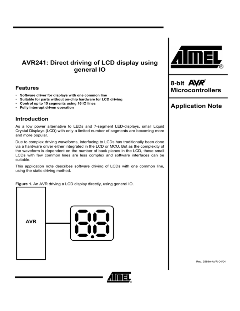
Figure 1. An AVR driving a LCD display directly, using general IO.
AVR
Rev. 2569A-AVR-04/04
Theory of operation
This section provides an overview of common features and a introduction to
terminology used in relation to LCD glass. Theory will focus upon driving of LCD glass
with one common line.
Terminology used in
relation to LCD
This section describes the terminology used throughout this document.
Segment
One of the bars/dots in a LCD display, controlled individually.
Frame
A frame is equivalent to one period of the cyclic waveform that is written to a
segment. Figure 2 gives a further explanation of what a frame is.
Frame rate
Frame rate is the number of frames per second. The frame rate should normally be
kept high enough to avoid that the human eye perceives the segments as flickering
and low enough to avoid ghosting. Ghosting occurs when segments are energized
due to cross talk between segment lines.
The frame rate should normally be kept between 30 and 100 Hz.
Common line
Electrical connection terminal shared by all display segments.
Segment line
Electrical connection terminal connected to a single segment.
LCD glass
The LCD is based upon a display technology that uses rod-shaped molecules (liquid
crystals) that flow like liquid and bend light. Non-energized, the crystals direct light
through two polarization filters, allowing a natural background color to show, making it
invisible. When energized, they redirect the light to be absorbed in one of the
polarizers, causing the dark appearance making it visible. The smallest viewing
element that can be turned visible/invisible (energized/non-energized) is referred to
as a display segment.
Each display segment has two connection terminals. One terminal is connected to a
segment driver and the other to a common terminal. One common terminal is shared
by a number of segments. Applying a voltage between the common terminal and a
segment terminal energizes the segment. Additionally the segment voltage has to be
alternated. DC (direct current) will cause electrophoresis effects in the liquid crystal
and will degrade the display. Consequently the voltages on both the common terminal
and the segment terminals must alter.
There are basically two driving methods for displays: Static and multiplexed. In the
multiplexed driving method many displays share segment lines, and the controlling of
several common lines multiplexes the displays. This method will need a variety of
complex waveforms and multiple analog levels to be sent to the display. In the static
driving method only one common line is used and each display segment will have
their unique terminal. This method will need relatively simple waveforms applied to
terminals. However, the static driving method is not suitable for LCDs with many
segments since each segment will need one dedicated output-pin from the MCU.
For more LCD theory please refer to application note AVR065: LCD Driver for the
STK502 and AVR Butterfly.
This application note will use the static driving method.
Figure 2 shows energized and non-energized segments and their driving waveforms.
2
AVR241
2569A-AVR-04/04
AVR241
Figure 2. 2 segments connected to 1 common terminal.
Segment line 1
Common line
Seg1
Seg0
Segment line 0
NonEnergized
energized segment
segment
Vlcd
Vlcd
Seg 0
Seg 1
Gnd
Gnd
Vlcd
Vlcd
Com
Com
Gnd
Gnd
Vlcd
Vlcd
Seg 0 Com
Gnd
-Vlcd
Seg 1 Com
Gnd
-Vlcd
Frame
Frame
Frame
Frame
3
2569A-AVR-04/04
Power consumption
Figure 3 shows a simplified equivalent circuit for a LCD. For a RC network like this
the main power consumption will occur in the region where the input waveforms are
toggling due to increased current through C1 and C2, hence lowering the LCD frame
rate will decrease the power consumption. In general the frame rate should be kept
above 30Hz to avoid display flickering. Though, in low power applications (e.g. battery
applications) the frame rate could be less than 30Hz as long as the display
contrast/flickering is satisfying for the given application.
R1: Segment- and common-plane resistance.
R2: Liquid crystal resistance.
C1: Barrier- and alignment-layer capacitance.
C2: Liquid crystal capacitance.
Figure 3. Simplified LCD equivalent circuit.
C1
R1
Segment line
R2
C2
Common line
4
AVR241
2569A-AVR-04/04
AVR241
Implementation
This section contains a description on how to connect a LCD to the AVR and how the
software should be implemented. The application can be tested directly on a STK500
with a single-common LCD connected. Program code is written in C for the IAR
EWAVR v. 2.28A, but other compilers can be used with only minor changes of the
code. This application note is made with an ATmega16, but any AVR microcontroller
with sufficient number of IO pins may be used. The software is tested with a LCD type
S5080D from Clover Display.
Physical connection
The application describes driving of 15 segments forming a 2x7-segment display + 1
“dot” segment as shown in figure 2. Controlling of all 15 segments and the common
line requires 16 I/O pins. This number can be reduced in applications where a lower
number of LCD-segments are required. Software contains functions for easy writing
of data to the LCD.
Figure 4. Physical connection of a 2x7+1 segment LCD. “Dot”-segment on digit 1 is
not connected.
VCC
AVR
PB0:PB6
DIG2A:
DIG2G
PB7
DOT2
PD7
COM
a
f
g
a
b
f
e
d
g
b
1
DIG1A:
DIG1G
1
PD0:PD6
c e
DIG1 DOT2
d
c
DIG2
LCD
GND
5
2569A-AVR-04/04
Firmware description
The LCD driver software is interrupt driven and suitable for use in low power
applications. The software consists of the function LCD_print() which is the driver
interface and the function LCD_update() which is used by the driver to write to the
LCD.
Including the driver in an existing application is done as follows:
1. Add LCD_drive.c to the project and LCD_drive.h to the include files.
2. Set up a timer interrupt as described in section below.
3. Call the function LCD_update() once for each timer interrupt.
4. Print to LCD by using the function LCD_print().
LCD_main.c shows an implementation of this application on an ATmega16 running
from the internal 1Mhz RC-oscillator.
LCD driver interface
Table 1. LCD driver C function description.
Function
Arguments
Return
LCD_print(global)
Unsigned char digit, Unsigned char ASCII_data
Unsigned char
LCD_print() is used by the main application to prepare data for LCD_update(). The
function receives ASCII values for the LCD to display, converts it to segment patterns
and initiates a LCD update.
Input arguments for LCD_print describe what digit to access (char digit) and what
ASCII value (char ASCII_data) to output on the digit. The digit number to access
should be in the range [1,2]. Figure 4 shows the digit numbering. The ASCII input
needs to follow certain rules to match the LCD:
5. Bit 0:6 should contain a 7-bit ASCII code in the range given by Table 2.
6. Bit 7 turns the LCD “dot”-segment on/off. Bit 7 = 1 turns “dot”-segment ON and bit
7 = 0 turns “dot”-segment OFF.
Notice that only “dot”-segment for digit 2 can be written. ASCI_data:7 should always
be 0 when printing to digit 1.
The functions return value is “1” for success and “0” for failure. Failure means that the
input arguments are outside the range described above or that the “dot”-segment on
digit 1 is signaled to be switched “ON”.
6
AVR241
2569A-AVR-04/04
AVR241
Table 2. LCD output given by input argument ASCII_data to function LCD_print().
Input character
(7 bit ASCII)
Input character
(7 bit ASCII)
LCD output
'0'
'9'
'1'
'A'
'2'
'B'
'3'
'C'
'4'
'D'
'5'
'E'
'6'
'F'
'7'
' ' (Space)
LCD output
(Blank)
'8'
LCD_update
Table 3. LCD driver C function description.
Function
Arguments
Return
LCD_update()
Void
Void
LCD_update() reads the global struct variable maintained by LCD_print() and
outputs them to the port pins driving the LCD. The function generates the LCD driving
frames and need to be called by a Timer/Counter interrupt to ensure a stable frame
rate.
7
2569A-AVR-04/04
Setting up the timer interrupt
In order to obtain a 50% duty cycle driving waveform as shown in Figure 2, some of
the code should be implemented within a timer interrupt service routine. The display
outputs have to be updated twice within each LCD frame. This means that the
interrupt frequency has to be twice the LCD frame rate. Considerations to make when
selecting frame rate is given in the theory section above. For most applications the
frame rate should be approximately 30Hz giving a interrupt frequency at 60 Hz.
The function LCD_update() should be called once for each timer interrupt.
Example program
The example program LCD_main.c, provided with this application note, shows an
implementation of the driver software in an ATmega16. TCNT0 is configured to
generate an interrupt every 17mS using the internal 1MHz RC-oscillator as clock
source.
The LCD is written to by the main application by using the function LCD_print().
8
AVR241
2569A-AVR-04/04
AVR241
Flowchart for function
LCD_print()
Figure 5. Flowchart for function LCD_print().
LCD_print()
"Dig" range
OK?
No
Return 0
Yes
Dot "ON" on
dig 1?
Yes
Return 0
No
"ASCI_data"
range OK?
No
Return 0
Yes
Data_var = Pattern
depended upon
"ASCII_data"
dig == 1?
No
Yes
LCD.digit1 =
Data_var
LCD.digit2 = Data
var | "Dot bit"
Return 1
9
2569A-AVR-04/04
Flowchart for function
LCD_update()
Figure 6. Flowchart for function LCD_update()
LCD_update(void)
Seq = 0?
No
Yes
Set outputs given
by global LCD
data variables.
Toggle PORTB
Toggle PORTD
Seq=1;
Seq=0;
Return
Flowchart for example
program
Figure 7. Flowchart for example program.
Start
TCNT0 IRQ
Config. sleep
mode
LCD_update();
Set up TCNT0
IRQ every 17 mS
Return from IRQ
Port init:
PORTB -> output
PORTD -> output
LCD_print();
Enable global IRQ
Sleep
10
AVR241
2569A-AVR-04/04
Atmel Corporation
2325 Orchard Parkway
San Jose, CA 95131, USA
Tel: 1(408) 441-0311
Fax: 1(408) 487-2600
Regional Headquarters
Europe
Atmel Sarl
Route des Arsenaux 41
Case Postale 80
CH-1705 Fribourg
Switzerland
Tel: (41) 26-426-5555
Fax: (41) 26-426-5500
Asia
Room 1219
Chinachem Golden Plaza
77 Mody Road Tsimshatsui
East Kowloon
Hong Kong
Tel: (852) 2721-9778
Fax: (852) 2722-1369
Japan
9F, Tonetsu Shinkawa Bldg.
1-24-8 Shinkawa
Chuo-ku, Tokyo 104-0033
Japan
Tel: (81) 3-3523-3551
Fax: (81) 3-3523-7581
Atmel Operations
Memory
2325 Orchard Parkway
San Jose, CA 95131, USA
Tel: 1(408) 441-0311
Fax: 1(408) 436-4314
Microcontrollers
2325 Orchard Parkway
San Jose, CA 95131, USA
Tel: 1(408) 441-0311
Fax: 1(408) 436-4314
La Chantrerie
BP 70602
44306 Nantes Cedex 3, France
Tel: (33) 2-40-18-18-18
Fax: (33) 2-40-18-19-60
ASIC/ASSP/Smart Cards
Zone Industrielle
13106 Rousset Cedex, France
Tel: (33) 4-42-53-60-00
Fax: (33) 4-42-53-60-01
RF/Automotive
Theresienstrasse 2
Postfach 3535
74025 Heilbronn, Germany
Tel: (49) 71-31-67-0
Fax: (49) 71-31-67-2340
1150 East Cheyenne Mtn. Blvd.
Colorado Springs, CO 80906, USA
Tel: 1(719) 576-3300
Fax: 1(719) 540-1759
Biometrics/Imaging/Hi-Rel MPU/
High Speed Converters/RF Datacom
Avenue de Rochepleine
BP 123
38521 Saint-Egreve Cedex, France
Tel: (33) 4-76-58-30-00
Fax: (33) 4-76-58-34-80
1150 East Cheyenne Mtn. Blvd.
Colorado Springs, CO 80906, USA
Tel: 1(719) 576-3300
Fax: 1(719) 540-1759
Scottish Enterprise Technology Park
Maxwell Building
East Kilbride G75 0QR, Scotland
Tel: (44) 1355-803-000
Fax: (44) 1355-242-743
Literature Requests
www.atmel.com/literature
Disclaimer: Atmel Corporation makes no warranty for the use of its products, other than those expressly contained in the Company’s standard
warranty which is detailed in Atmel’s Terms and Conditions located on the Company’s web site. The Company assumes no responsibility for
any errors which may appear in this document, reserves the right to change devices or specifications detailed herein at any time without notice,
and does not make any commitment to update the information contained herein. No licenses to patents or other intellectual property of Atmel
are granted by the Company in connection with the sale of Atmel products, expressly or by implication. Atmel’s products are not authorized for
use as critical components in life support devices or systems.
© Atmel Corporation 2004. All rights reserved. Atmel® and combinations thereof, AVR® , and AVR Studio® are the registered
trademarks of Atmel Corporation or its subsidiaries. Microsoft® , Windows® , Windows NT® , and Windows XP® are the registered trademarks
of Microsoft Corporation. Other terms and product names may be the trademarks of others
2569A-AVR-04/04


