LMR Electric Fire Pump Controllers Features
advertisement
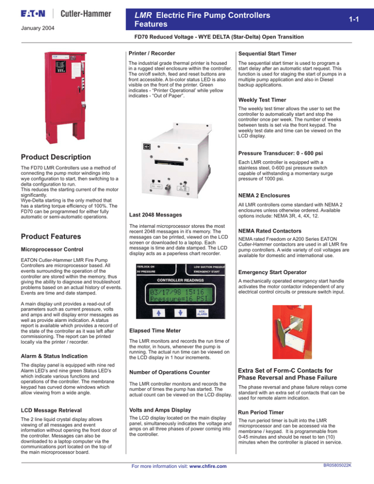
January 2004 LMR Electric Fire Pump Controllers Features 1-1 FD70 Reduced Voltage - WYE DELTA (Star-Delta) Open Transition Printer / Recorder Sequential Start Timer The industrial grade thermal printer is housed in a rugged steel enclosure within the controller. The on/off switch, feed and reset buttons are front accessible. A bi-color status LED is also visible on the front of the printer. Green indicates - “Printer Operational’ while yellow indicates - “Out of Paper”. The sequential start timer is used to program a start delay after an automatic start request. This function is used for staging the start of pumps in a multiple pump application and also in Diesel backup applications. Weekly Test Timer The weekly test timer allows the user to set the controller to automatically start and stop the controller once per week. The number of weeks between tests is set via the front keypad. The weekly test date and time can be viewed on the LCD display. Pressure Transducer: 0 - 600 psi Product Description The FD70 LMR Controllers use a method of connecting the pump motor windings into wye configuration to start, then switching to a delta configuration to run. This reduces the starting current of the motor significantly. Wye-Delta starting is the only method that has a starting torque efficiency of 100%. The FD70 can be programmed for either fully automatic or semi-automatic operations. Product Features Microprocessor Control Each LMR controller is equipped with a stainless steel, 0-600 psi pressure switch capable of withstanding a momentary surge pressure of 1000 psi. NEMA 2 Enclosures Last 2048 Messages The internal microprocessor stores the most recent 2048 messages in it’s memory. The messages can be printed, viewed on the LCD screen or downloaded to a laptop. Each message is time and date stamped. The LCD display acts as a paperless chart recorder. EATON Cutler-Hammer LMR Fire Pump Controllers are microprocessor based. All events surrounding the operation of the controller are stored within the memory, thus giving the ability to diagnose and troubleshoot problems based on an actual history of events. Events are time and date stamped. A main display unit provides a read-out of parameters such as current pressure, volts and amps and will display error messages as well as provide alarm indication. A status report is available which provides a record of the state of the controller as it was left after commissioning. The report can be printed locally via the printer / recorder. Alarm & Status Indication The display panel is equipped with nine red Alarm LED’s and nine green Status LED’s which indicate various functions and operations of the controller. The membrane keypad has curved dome windows which allow viewing from a wide angle. All LMR controllers come standard with NEMA 2 enclosures unless otherwise ordered. Available options include: NEMA 3R, 4, 4X, 12. NEMA Rated Contactors NEMA rated Freedom or A200 Series EATON Cutler-Hammer contactors are used in all LMR fire pump controllers. A wide variety of coil voltages are available for domestic and international use. Emergency Start Operator A mechanically operated emergency start handle activates the motor contactor independent of any electrical control circuits or pressure switch input. Elapsed Time Meter The LMR monitors and records the run time of the motor, in hours, whenever the pump is running. The actual run time can be viewed on the LCD display in 1 hour increments. Number of Operations Counter The LMR controller monitors and records the number of times the pump has started. The actual count can be viewed on the LCD display. LCD Message Retrieval Volts and Amps Display The 2 line liquid crystal display allows viewing of all messages and event information without opening the front door of the controller. Messages can also be downloaded to a laptop computer via the communications port located on the top of the main microprocessor board. The LCD display located on the main display panel, simultaneously indicates the voltage and amps on all three phases of power coming into the controller. For more information visit: www.chfire.com Extra Set of Form-C Contacts for Phase Reversal and Phase Failure The phase reversal and phase failure relays come standard with an extra set of contacts that can be used for remote alarm indication. Run Period Timer The run period timer is built into the LMR microprocessor and can be accessed via the membrane / keypad. It is programmable from 0-45 minutes and should be reset to ten (10) minutes when the controller is placed in service. BR05805022K 1-2 LMR Electric Fire Pump Controllers Features January 2004 FD70 Reduced Voltage - WYE DELTA (Star-Delta) Open Transition Product Features Status & Alarm Indication Additional Output Relay An additional output relay labeled Future #1, can be user programmed to operate for nine (9) different functions. Programming is done in the LMR menu using the membrane / keypad. Common Alarm Relay and Contacts The LMR controller has a common alarm relay which energizes whenever there are any alarm conditions present. This relay is energized under normal conditions and has LED status indication on the main relay board. Status LED’s Alarm LED’s Power On Pump Running RPT Timer Sequence Timer Local Start Remote Start Deluge Valve Interlock On Low Pressure Phase Reversal Phase Failure Fail To Start Undervoltage Overvoltage Relief Valve Discharge Locked Rotor Trip Low Suction Pressure Emergency Start Pressure 102 PSI Technical Data and Specifications Line Terminals (Incoming Cables) Line Terminals on Main Isolation Switch (Incoming Cables) LINE VOLTAGE Max. Hp 200 - 208 220 - 240 Qty. & Cable Sizes 380 - 415 440 - 480 550 - 600 (CU/AL) 30 30 60 75 100 (1)#14-1/0 PER 40 40 100 100 - (1)#4-4/0 PER (CU/AL) (1)#14-2/0 (CU/AL) 75 75 150 200 200 (1)#3-350MCM (CU/AL) (1)#4-350MCM (CU/AL) 100 100 200 250 300 (2)3/0-250MCM (CU/AL) (2)#4-350MCM (CU/AL) 150 150 350 400 400 (2)250-350MCM (CU/AL) (2)#2-600MCM (CU/AL) * Coils available: 380V-50Hz, 380V-60Hz, 415V-50Hz, 415V-60Hz. Load Terminals (To Motor) Load Terminals (To Motor) LINE VOLTAGE Max. Hp Qty. & Cable Sizes 200 - 208 220 - 240 380 - 415 440 - 480 550 - 600 25 30 60 60 75 (1)#14-#3 PER 50 60 100 125 150 (1)#14-1/0 PER (CU/AL) (CU/AL) 75 100 200 200 250 (1)#6-250MCM (CU/AL) 150 200 350 400 400 (2)1/0-250MCM (CU/AL) F o r P r o p e r Cable Size Refer to National Electrical Code NFPA-70 Standards & Certification The LMR Electric Fire Pump Controllers meet or exceed the requirements of Underwriters Laboratories, Underwriters Laboratories Canada, Factory Mutual, the Canadian Standards Association, New York City building code, CE mark requirements and are built to NFPA 20 standards. BR05805022K Service Entrance GND.LUG Qty. & Cable Sizes N. Y. C. APPROVED For more information visit: www.chfire.com (1)#14-2/0 (CU/AL) LMR Electric Fire Pump Controllers Features January 2004 1-3 FD70 Reduced Voltage - WYE DELTA (Star-Delta) Open Transition Dimensions Standard Enclosure - Type NEMA 2, 3R, 4, 4X, 12 Fire Pump Controller Fire Pump Controller LMR SWITCH/CIRCUIT BREAKER (DISCONNECTING MEANS) SWITCH/CIRCUIT BREAKER (DISCONNECTING MEANS) OPERATION INSTRUCTIONS Motor Hp OPERATION INSTRUCTIONS TO PLACE IN SERVICE TO PLACE IN SERVICE TO START NON-AUTOMATIC OPERATION TO START NON-AUTOMATIC OPERATION TO RETURN TO AUTOMATIC OPERATION TO RETURN TO AUTOMATIC OPERATION TO TAKE OUT OF SERVICE TO TAKE OUT OF SERVICE Line Voltage Withstand Rating Standard Intermediate High 5 - 40 200 - 208V 100,000 150,000 5 - 50 220 - 240V 5 - 75 * 380 - 415V 5 - 75 440 - 480V 5 - 75 550 - 600V 25,000 100,000 100 440 - 480V 100,000 150,000 100 550 - 600V 25,000 100,000 200,000 Approx. Weight Lbs. (Kg) A B C D 350 (159) 31.51 (800) 26.50 (673) 21.00 (533) 16.86 (428) 37.01 (940) 32.00 (813) 26.50 (673) 22.36 (568) * Coils available: 380V-50Hz, 380V-60Hz, 415V-50Hz, 415V-60Hz. NOTES: 1. All enclosures finished in FirePump red. 2. Cable Entrance either top or bottom. 3. Standard Enclosure type NEMA 2. N. Y. C. APPROVED For more information visit: www.chfire.com BR05805022K 1-4 LMR Electric Fire Pump Controllers Features January 2004 FD70 Reduced Voltage - WYE DELTA (Star-Delta) Open Transition Dimensions Standard Enclosure - Type NEMA 2, 3R, 4, 4X, 12 Fire Pump Controller Fire Pump Controller LMR SWITCH/CIRCUIT BREAKER (DISCONNECTING MEANS) SWITCH/CIRCUIT BREAKER (DISCONNECTING MEANS) OPERATION INSTRUCTIONS OPERATION INSTRUCTIONS TO PLACE IN SERVICE TO PLACE IN SERVICE TO START NON-AUTOMATIC OPERATION Motor Hp TO RETURN TO AUTOMATIC OPERATION TO TAKE OUT OF SERVICE TO TAKE OUT OF SERVICE Line Voltage Withstand Rating Standard Intermediate High 50 - 100 200 - 208V 100,000 60 - 125 220 - 240V Consult Factory 100 - 200 TO START NON-AUTOMATIC OPERATION TO RETURN TO AUTOMATIC OPERATION Consult Factory Approx. Weight Lbs. (Kg) A B C D 605 (274) 47.85 (1215) 37.23 (946) 11.00 (279) 27.10 (688) 710 (322) 53.85 (1368) 43.23 (1098) 21.74 (552) 33.10 (841) * 380 - 415V 125 - 250 440 - 480V 125 - 300 550 - 600V 25,000 35,000 125 - 200 200 - 208V 100,000 150 - 200 220 - 240V Consult Factory 25,000 35,000 250 - 400 * 380 - 415V 300 - 400 440 - 480V 350 - 400 550 - 600V * Coils available: 380V-50Hz, 380V-60Hz, 415V-50Hz, 415V-60Hz. NOTES: 1. All enclosures finished in FirePump red. 2. Cable Entrance either top or bottom. 3. Standard Enclosure type NEMA 2. N. Y. C. APPROVED BR05805022K For more information visit: www.chfire.com LMR Electric Fire Pump Controllers Features January 2004 1- 5 FD70 Reduced Voltage - WYE DELTA (Star-Delta) Open Transition Dimensions Standard Enclosure - Type NEMA 2, 3R, 4, 4X, 12 Fire Pump Controller Fire Pump Controller LMR SWITCH/CIRCUIT BREAKER (DISCONNECTING MEANS) SWITCH/CIRCUIT BREAKER (DISCONNECTING MEANS) OPERATION INSTRUCTIONS OPERATION INSTRUCTIONS TO PLACE IN SERVICE TO PLACE IN SERVICE TO START NON-AUTOMATIC OPERATION Motor Hp Line Voltage 200 - 250 200 - 208V 250 - 300 220 - 240V 350 - 500 * 380 - 415V 450 - 600 440 - 480V 550 - 700 550 - 600V TO START NON-AUTOMATIC OPERATION TO RETURN TO AUTOMATIC OPERATION TO RETURN TO AUTOMATIC OPERATION TO TAKE OUT OF SERVICE TO TAKE OUT OF SERVICE Withstand Rating Standard Intermediate High Approx. Weight Lbs. (Kg) 100,000 Consult Factory 865 Consult Factory (392) 25,000 35,000 * Coils available: 380V-50Hz, 380V-60Hz, 415V-50Hz, 415V-60Hz. NOTES: 1. All enclosures finished in FirePump red. 2. Cable Entrance either top or bottom. 3. Standard Enclosure type NEMA 2. N. Y. C. APPROVED For more information visit: www.chfire.com BR05805022K 1-6 LMR Electric Fire Pump Controllers Features January 2004 FD70 Reduced Voltage - WYE DELTA (Star-Delta) Open Transition MAIN BOARD RELAY CARD Electrical Wiring Schematic N. Y. C. APPROVED BR05805022K For more information visit: www.chfire.com LMR Electric Fire Pump Controllers Features January 2004 1-7 FD70 Reduced Voltage - WYE DELTA (Star-Delta) Open Transition Electric Motor Connections Wye-Delta Lower Nameplate Voltage NOTE: 1. MOTOR CONNECTIONS VARY PLEASE REFER TO SPECIFIC MOTOR MANUFACTURER'S CONNECTION DIAGRAM. 2. FOR SINGLE VOLTAGE 12 LEAD MOTORS USE LOWER VOLTAGE CONNECTION DIAGRAM Wye-Delta Higher Nameplate Voltage NOTE: 1. MOTOR CONNECTIONS VARY PLEASE REFER TO SPECIFIC MOTOR MANUFACTURER'S CONNECTION DIAGRAM. 2. FOR SINGLE VOLTAGE 12 LEAD MOTORS USE LOWER VOLTAGE CONNECTION DIAGRAM N. Y. C. APPROVED For more information visit: www.chfire.com BR05805022K 1-8 LMR Electric Fire Pump Controllers Features January 2004 FD70 Reduced Voltage - WYE DELTA (Star-Delta) Open Transition Options - Wiring Diagram Main Terminal Block: TB1 Typical Controller Connection NOTES: 1. Terminal 49 is common to all dry contact inputs. DO NOT APPLY A VOLTAGE ON THESE TERMINALS 2. Contacts shown in de-energized state (Fail Safe). Relay Card NOTES: 1. To Control Circuit 2. Spare for Customer Connections 3. To TB1 4. To Shunt Trip 5. Contacts Shown in De-Energized State - (Fail Safe) BR05805022K For more information visit: www.chfire.com LMR Electric Fire Pump Controllers Features January 2004 1-9 FD70 Reduced Voltage - WYE DELTA (Star-Delta) Open Transition Catalog Number Selection FD70 WYE DELTA (Star-Delta) Controller Catalog Numbering System FD LMR Type 70 = WYE DELTA (Star-Delta) Open A B C1 C2 C3 C4 C5 E1 E2 Horsepower 15 20 40 50 100 125 250 300 450 500 25 30 60 75 150 200 350 400 600 700 - E3 E5 - A= B= C= D= E= E8 E9 - Voltage 200 - 208V 60 HZ 220 - 240V 60 HZ 380 - 415V 50/60 HZ 440 - 480V 60 HZ 550 - 600V 60 HZ E10 - LMR Series Microprocessor Control Language L1 = English L2 = French L5 = Spanish EX F F2 H I P7 P8 P10 P13 R1 R2 R3 R4 X1 X2 - For more information visit: www.chfire.com Options Built-in Alarm System Alarm Bell Extra Contacts "Pump Run" (one N.O. std.) Extra Contacts "AC Power Failure" (two sets std.) Extra Contacts "Phase Rev." (two sets std.) Remote Contacts (2 Form C) Low Reservoir Remote Contacts (2 Form C) High Reservoir NEMA 3R - Raintight Enclosure NEMA 4 - Watertight Enclosure (Ref Dwg. Page 1-3) NEMA 4 - Watertight Enclosure (Ref Dwg. Page 1-4) NEMA 12 - Industrial Dust Tight Enclosure NEMA 4X - Stainless Steel Enclosure (Ref. Dwg.page 1-3) NEMA 4X - Stainless Steel Enclosure (Ref Dwg. Page 1-4) Tropicalization NEMA 4X - Painted Steel (Ref. Dwg. Page 1-3) NEMA 4X - Painted Steel (Ref. Dwg. Page 1-4) NEMA 4X - 316 Stainless Steel Enclosure (Ref. Dwgs Page 1-3) NEMA 4X - 316 Stainless Steel Enclosure (Ref. Dwg. Page 1-4) Export Crating Floor Stand (Standard c/w floor mounted enclosures) Floor Stand - 2 Inch Height High Withstand Rating (refer to tables) Intermediate Withstand Rating (refer to tables) Low Suction Pressure Switch c/w Pilot Light Low Suction Shutdown (Requires P7) Pressure Transducer - Sea Water Rated Externally Mounted Pressure Transducer Space Heater (120 / 220V) Space Heater c/w Thermostat Space Heater c/w Humidistat Low Pump Room Temperature Switch and Pilot Light Printer/Pressure Recorder (Standard on LMR FM Units) 4 - Inch Chart Recorder (10 - 300 psi fresh water) BR05805022K
