EECS 211 Circuits I Spring Semester 2014 Assignment #3 Due 11
advertisement

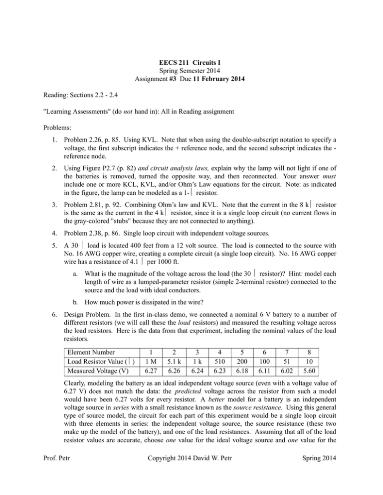
EECS 211 Circuits I Spring Semester 2014 Assignment #3 Due 11 February 2014 Reading: Sections 2.2 - 2.4 "Learning Assessments" (do not hand in): All in Reading assignment Problems: 1. Problem 2.26, p. 85. Using KVL. Note that when using the double-subscript notation to specify a voltage, the first subscript indicates the + reference node, and the second subscript indicates the reference node. 2. Using Figure P2.7 (p. 82) and circuit analysis laws, explain why the lamp will not light if one of the batteries is removed, turned the opposite way, and then reconnected. Your answer must include one or more KCL, KVL, and/or Ohm’s Law equations for the circuit. Note: as indicated in the figure, the lamp can be modeled as a 1-Ω resistor. 3. Problem 2.81, p. 92. Combining Ohm’s law and KVL. Note that the current in the 8 kΩ resistor is the same as the current in the 4 kΩ resistor, since it is a single loop circuit (no current flows in the gray-colored "stubs" because they are not connected to anything). 4. Problem 2.38, p. 86. Single loop circuit with independent voltage sources. 5. A 30 Ω load is located 400 feet from a 12 volt source. The load is connected to the source with No. 16 AWG copper wire, creating a complete circuit (a single loop circuit). No. 16 AWG copper wire has a resistance of 4.1 Ω per 1000 ft. 6. a. What is the magnitude of the voltage across the load (the 30 Ω resistor)? Hint: model each length of wire as a lumped-parameter resistor (simple 2-terminal resistor) connected to the source and the load with ideal conductors. b. How much power is dissipated in the wire? Design Problem. In the first in-class demo, we connected a nominal 6 V battery to a number of different resistors (we will call these the load resistors) and measured the resulting voltage across the load resistors. Here is the data from that experiment, including the nominal values of the load resistors. Element Number Load Resistor Value (Ω) Measured Voltage (V) 1 1M 6.27 2 5.1 k 6.26 3 1k 6.24 4 510 6.23 5 200 6.18 6 100 6.11 7 51 6.02 8 10 5.60 Clearly, modeling the battery as an ideal independent voltage source (even with a voltage value of 6.27 V) does not match the data: the predicted voltage across the resistor from such a model would have been 6.27 volts for every resistor. A better model for a battery is an independent voltage source in series with a small resistance known as the source resistance. Using this general type of source model, the circuit for each part of this experiment would be a single loop circuit with three elements in series: the independent voltage source, the source resistance (these two make up the model of the battery), and one of the load resistances. Assuming that all of the load resistor values are accurate, choose one value for the ideal voltage source and one value for the Prof. Petr Copyright 2014 David W. Petr Spring 2014 EECS 211 -2- Assignment #3 source resistance that will, on the whole, better predict the measured load resistor voltages. Hint: use voltage division. Your model will not perfectly predict the measured values, but it should come much closer. Using the model values that you have chosen (the one source voltage and the one source resistance), compare (in a table) the predicted load voltages (from your model) and the measured voltages. There is no single "right" answer. 7. Problem 2.41, p. 87. Single loop circuit with independent and dependent voltage sources. 8. Problem 2.82, p. 92. Combining Ohm’s Law and KCL. Note that the voltage across the 2 kΩ resistor is the same as the voltage across the 4 kΩ resistor, since there are only two nodes in this circuit (and hence only one voltage). 9. Problem 2.47, p. 87. Single node-pair circuit with independent source (current division). 10. One of your classmates (call him Jim) has worked out the solution to a current division problem as shown on the attached page. This problem will involve checking Jim’s answer. We will not simply re-work the problem as a current division problem; rather we will do some specific checks on his specific answer. Prof. Petr a. Check Jim’s answer for the two currents by checking KCL. Does this check seem to confirm Jim’s answer or does it indicate that it is incorrect? b. Now check Jim’s answer by computing the voltage across the 8 kΩ resistor and then the voltage across the 6 kΩ resistor, and then checking KVL. Does this check seem to confirm Jim’s answer or does it indicate that it is incorrect? Copyright 2014 David W. Petr Spring 2014


