MBS 33M Marine Pressure Transmitter Data Sheet
advertisement
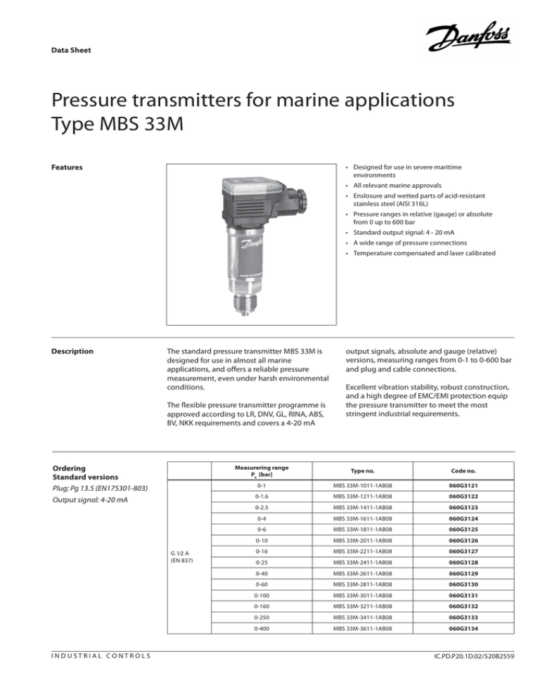
Data Sheet Pressure transmitters for marine applications Type MBS 33M Features • Designed for use in severe maritime environments • All relevant marine approvals • Enslosure and wetted parts of acid-resistant stainless steel (AISI 316L) • Pressure ranges in relative (gauge) or absolute from 0 up to 600 bar • Standard output signal: 4 - 20 mA • A wide range of pressure connections • Temperature compensated and laser calibrated Description The standard pressure transmitter MBS 33M is designed for use in almost all marine applications, and offers a reliable pressure measurement, even under harsh environmental conditions. The flexible pressure transmitter programme is approved according to LR, DNV, GL, RINA, ABS, BV, NKK requirements and covers a 4-20 mA Ordering Standard versions Plug; Pg 13.5 (EN175301-803) Output signal: 4-20 mA G 1⁄2 A (EN 837) INDUSTRIAL CONTROLS output signals, absolute and gauge (relative) versions, measuring ranges from 0-1 to 0-600 bar and plug and cable connections. Excellent vibration stability, robust construction, and a high degree of EMC/EMI protection equip the pressure transmitter to meet the most stringent industrial requirements. Measurering range Pe [bar] Type no. Code no. 0-1 MBS 33M-1011-1AB08 060G3121 0-1.6 MBS 33M-1211-1AB08 060G3122 0-2.5 MBS 33M-1411-1AB08 060G3123 0-4 MBS 33M-1611-1AB08 060G3124 0-6 MBS 33M-1811-1AB08 060G3125 0-10 MBS 33M-2011-1AB08 060G3126 0-16 MBS 33M-2211-1AB08 060G3127 0-25 MBS 33M-2411-1AB08 060G3128 0-40 MBS 33M-2611-1AB08 060G3129 0-60 MBS 33M-2811-1AB08 060G3130 0-100 MBS 33M-3011-1AB08 060G3131 0-160 MBS 33M-3211-1AB08 060G3132 0-250 MBS 33M-3411-1AB08 060G3133 0-400 MBS 33M-3611-1AB08 060G3134 IC.PD.P20.1D.02/520B2559 Data sheet Pressure transmitters for marine applications, Type MBS 33M Technical data Performance (EN 60770) Accuracy (incl. non-linearity, hysteresis and repeatability) Non-linearity BFSL (conformity) Hysteresis and repeatability Thermal zero point shift Thermal sensitivity (span) shift Response time Liquids with viscosity < 100 cSt Air and gases Overload pressure (Static) Burst pressure Durability, P: 10-90% FS ±0.5% FS (typ.) ±1% FS (max.) ≤ ±0.2% FS ≤ ±0.1% FS ≤ ±0.1% FS/10K (typ.) ≤ ±0.2% FS/10K (max.) ≤ ±0.1% FS/10K (typ.) ≤ ±0.2% FS/10K (max.) < 4 ms < 35 ms 6 × FS (max. 1500 bar) > 6 × FS (max. 2000 bar) >10×106 cycles Electrical specifications Nom. output signal (short circuit protected) Supply voltage VB (polarity protected) Voltage dependency 4-20 mA 10-30 V dc <0.05% FS/10 V Current limitation (linear output signal up to 1.5 x rated range) Load resistance [RL] (Load connected 0 V) RL ≤ 28 mA UB - 10V 0.02 A [Ω] Environmental conditions Medium temperature range Ambient temperature range (depending on electrical connection) Compensated temperature range Transport temperature range EMC - Emission EMC Immunity Insulation resistance Mains frequency test 15.9 mm-pp, 5 Hz-25 Hz Vibration stability Sinusoidal 20 g, 25 Hz - 2 kHz Random 7.5 grms, 5Hz-1kHz Shock 500 g / 1 ms Shock resistance Free fall Enclosure (depending on electrical connection) −40 → +85°C see page 4 0 → +80°C −50 → +85°C EN 61000-6-3 EN 61000-6-2 > 100 MΩ at 100 V SEN 361503 IEC 60068-2-6 IEC 60068-2-34, IEC 60068-2-36 IEC 60068 - 2 - 27 IEC 60068 - 2 - 32 see page 4 Mechanical characteristics Wetted parts Enclosure Electrical connections Weight (depending on pressure connection and electrical connection) Materials 2 EN 10088-1; 1.4404 (AISI 316 L) EN 10088-1; 1.4404 (AISI 316 L) see page 4 0.2 - 0.3 kg IC.PD.P20.1D.02/520B2559 Data sheet Pressure transmitters for marine applications, Type MBS 33M Ordering, Special versions MBS 33MMeasuring range Preferred versions Non-standard build-up combinations may be selected. However, minimum order quantities may apply. Please contact your local Danfoss office for further information or request on other versions. Pressure connection 0 - 1 bar.................................. 1 0 A B 0 4 ...........................................................................G ¼ A (EN 837) 0 - 1.6 bar............................... 1 2 A B 0 8 ...........................................................................G ½ A (EN 837) 0 - 2.5 bar.............................. 1 4 A C 0 4 ....................................................................................¼ - 18 NPT 0 - 4 bar................................ 1 6 A C 0 8 ...............................½ -14 NPT 0 - 6 bar................................ 1 8 G B 0 4 ........................DIN 3852-E-G¼ ; gasket DIN 3869-14 NBR 0 - 10 bar............................... 2 0 0 - 16 bar................................ 2 2 0 - 25 bar................................ 2 4 Electrical connection 0 - 40 bar................................ 2 6 Figures refer to plug and standard PIN configuration - see page 4 0 - 60 bar............................... 2 8 1 .........................................................................................Plug Pg 13.5 EN175301-803) 0 - 100 bar............................. 3 0 3 ..........................................................................................................Screened cable, 2 m 0 - 160 bar............................. 3 2 5 ............................................................................................Plug PG 9 (EN 175301-803) 0 - 250 bar............................. 3 4 6 ...........................................................................................Plug PG 11 (EN 175301-803) 0 - 400 bar............................. 3 6 0 - 600 bar............................. 3 8 Output signal 1 ...........................................................................................................................................4-20 mA Pressure reference Gauge (relative)......................................... 1 Absolute....................................................... 2 Dimensions/combinations Type code Type code IC.PD.P20.1D.02/520B2559 1 3 5 6 EN175301-803, Pg13.5 2 m screened cable EN175301-803, Pg 9 EN175301-803, Pg 11 G¼A G½A (EN 837) (EN 837) AB04 AB08 ¼-18 NPT ½-14 NPT DIN 3852-E-G¼ Gasket: DIN 3869-14 NBR, O-ring AC04 AC08 GB04 3 Data sheet Pressure transmitters for marine applications, Type MBS 33M Electrical connections Type code page 3 1 EN 175301-803, Pg9 3 2 m screened cable 5 6 -40 to +85 °C -30 to +85 °C -40 to +85 °C -40 to +85 °C IP 65 IP 67 IP 65 IP 65 Glass filled polyamid, PA 6.6 Poliolyfin cable with PE shirnkage tubing Glass filled polyamid, PA 6.6 Glass filled polyamid, PA 6.6 Ambient temperature Enclosure Materials Electrical connection, 4-20 mA output (2 wire) Pin 1: +supply Brown wire: + supply Pin 1: +supply Pin 1: +supply Pin 2: ÷supply Black wire: ÷supply Pin 2: ÷supply Pin 2: ÷supply Pin 3: Not used Red wire: Not used Pin 3: Not used Pin 3: Not used Earth: Connected to MBS enclosure Orange: Not used Earth: Connected to MBS enclosure Earth: Connected to MBS enclosure Screen: Not connected to © Danfoss A/S 02-2006 IC-MC/mr MBS enclosure 4 IC.PD.P20.1D.02/520B2559

