Mag-Head Assembly Replacement
advertisement

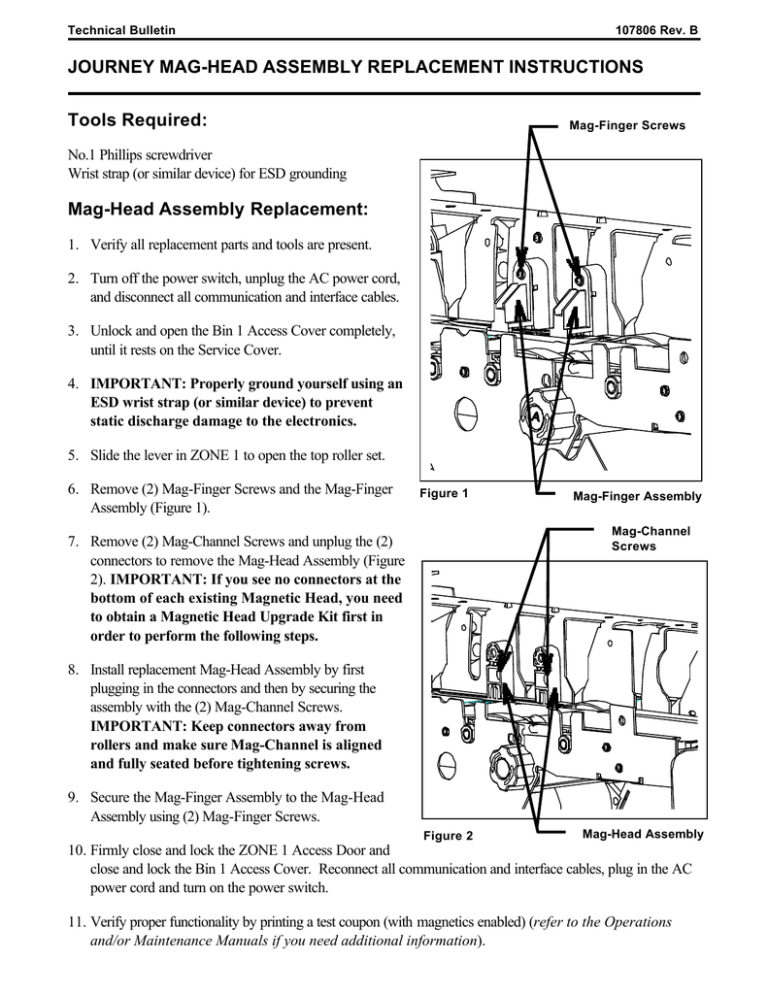
Technical Bulletin 107806 Rev. B JOURNEY MAG-HEAD ASSEMBLY REPLACEMENT INSTRUCTIONS Tools Required: Mag-Finger Screws No.1 Phillips screwdriver Wrist strap (or similar device) for ESD grounding Mag-Head Assembly Replacement: 1. Verify all replacement parts and tools are present. 2. Turn off the power switch, unplug the AC power cord, and disconnect all communication and interface cables. 3. Unlock and open the Bin 1 Access Cover completely, until it rests on the Service Cover. 4. IMPORTANT: Properly ground yourself using an ESD wrist strap (or similar device) to prevent static discharge damage to the electronics. 5. Slide the lever in ZONE 1 to open the top roller set. 6. Remove (2) Mag-Finger Screws and the Mag-Finger Assembly (Figure 1). Figure 1 Mag-Finger Assembly Mag-Channel Screws 7. Remove (2) Mag-Channel Screws and unplug the (2) connectors to remove the Mag-Head Assembly (Figure 2). IMPORTANT: If you see no connectors at the bottom of each existing Magnetic Head, you need to obtain a Magnetic Head Upgrade Kit first in order to perform the following steps. 8. Install replacement Mag-Head Assembly by first plugging in the connectors and then by securing the assembly with the (2) Mag-Channel Screws. IMPORTANT: Keep connectors away from rollers and make sure Mag-Channel is aligned and fully seated before tightening screws. 9. Secure the Mag-Finger Assembly to the Mag-Head Assembly using (2) Mag-Finger Screws. Figure 2 Mag-Head Assembly 10. Firmly close and lock the ZONE 1 Access Door and close and lock the Bin 1 Access Cover. Reconnect all communication and interface cables, plug in the AC power cord and turn on the power switch. 11. Verify proper functionality by printing a test coupon (with magnetics enabled) (refer to the Operations and/or Maintenance Manuals if you need additional information).


