General
Specifications
FO-529-02
GS48C29Z02-00E-N
Fail Safe Output Module (24 Vdc, 5W)
■
GENERAL
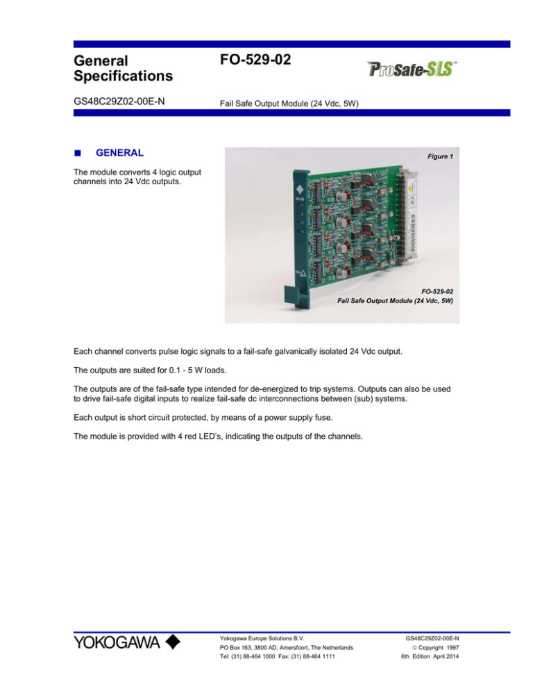
Figure 1
The module converts 4 logic output
channels into 24 Vdc outputs.
FO-529-02
Fail Safe Output Module (24 Vdc, 5W)
Each channel converts pulse logic signals to a fail-safe galvanically isolated 24 Vdc output.
The outputs are suited for 0.1 - 5 W loads.
The outputs are of the fail-safe type intended for de-energized to trip systems. Outputs can also be used
to drive fail-safe digital inputs to realize fail-safe dc interconnections between (sub) systems.
Each output is short circuit protected, by means of a power supply fuse.
The module is provided with 4 red LED’s, indicating the outputs of the channels.
Yokogawa Europe Solutions B.V.
PO Box 163, 3800 AD, Amersfoort, The Netherlands
Tel: (31) 88-464 1000 Fax: (31) 88-464 1111
GS48C29Z02-00E-N
Copyright 1997
6th Edition April 2014
FO-529-02
■
2 of 4
FUNCTIONAL DIAGRAM
Inputs
Module
Outputs
Supply
Notes
Front
z18
24 Vdc field
z28
0 Vdc field
Suppression diode for inductive loads is part of the rectifier circuit.
1 output circuit 1
z32
24 Vdc field
z30
0 Vdc field
b32
20 Vdc logic
5
d32
0 Vdc logic
6
d30
not used
7
b30
B voltage pulse
8
2 output circuit 2
In case of external fusing with AF-533: Remove fuses F1 – F4, do not connect z18, z32
All Rights Reserved. Copyright Yokogawa Europe Solutions B.V.
3 output circuit 3
4 output circuit 4
GS48C29Z02-00E-N April 2014
FO-529-02
■
3 of 4
SPECIFICATIONS
General
Environmental
Description
No. of channels
Size
Connector
Identification
Temperature (working)
Temperature (storage)
Relative humidity
EMC
Explosion protection
Data
4
single Euro format 3TE (160x100x15 mm)
DIN 41612 Bauform F 48p
FO-529 on front
-20 to +70 °C
-25 to +85 °C
max. 95%, no condensation
EN 61000-6-2 Immunity
EN 61000-6-4 Emission
(With an EMC system enclosure)
IECEx:
Ex nA IIC T4 Gc
IEC 60079-0 : 2011 Edition 6.0 IEC 60079-15 : 2010 Edition 4
ATEX:
Input
Output
Propagation
Supply
Isolation
Shock
Vibration
Pulse logic
Unit load
Output type
Voltage
Current
Minimum load
Isolation resistance
Efficiency
Converter frequency
Field supply fuse
Status indication
On delay
Off delay
Field supply
Logic supply
Clock signal
Pulse logic inputs
Isolated dc-outputs
Dissipation
All Rights Reserved. Copyright Yokogawa Europe Solutions B.V.
II 3 G Ex nA IIC T4 Gc
EN 60079-0 : 2012
EN 60079-15 : 2010
10g ; 16 ms
10-55 Hz ; ± 0.35 mm
current pulses 500 mA
1
isolated dc/dc-converter output, fail-safe
24 Vdc +10%, -5% and field voltage tolerance
max. 0.22 A (5.3 W load @ 24 Vdc)
0.1 W (4 mA @ 24 Vdc)
1 MΩ (minus terminal to 0V field)
> 85% @ full load
32 kHz
0.4 A fast per output
red LED per output
1 – 5 ms
5 – 15 ms @ full load
< 35 ms @ minimum load
24 Vdc ± 10% (+20% temporary)
max. 1 V top-top ripple
< 1 mA @ all channels off
60mA @ all channels no load
1.03 A @ all channels full load
fusing : see ‘Output’
20 Vdc, 1 mA
B voltage pulse
0.5 kV (test)
0.5 KV (test; note isolation resistance at ‘Output’)
3.5 W @ all channels full load
GS48C29Z02-00E-N April 2014
FO-529-02
■
4 of 4
NOTES
All Rights Reserved. Copyright Yokogawa Europe Solutions B.V.
GS48C29Z02-00E-N April 2014


