GE Energy
Digital Energy
Zenith ZTSCT
Closed Transition Transfer Switches
Introduction
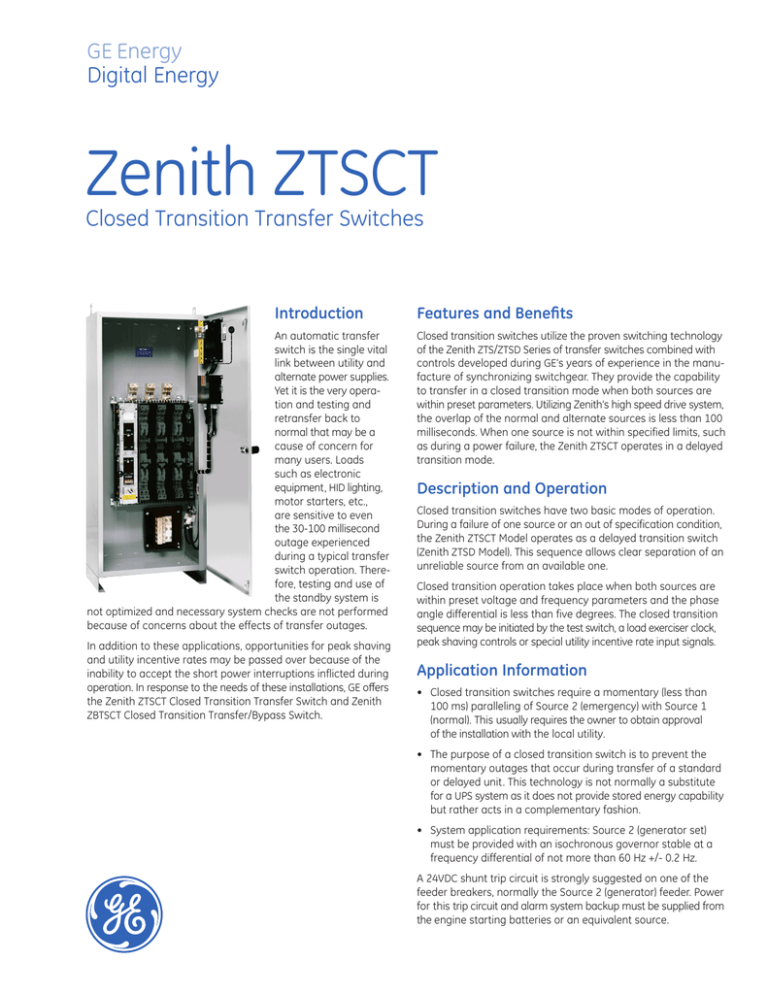
An automatic transfer
switch is the single vital
link between utility and
alternate power supplies.
Yet it is the very operation and testing and
retransfer back to
normal that may be a
cause of concern for
many users. Loads
such as electronic
equipment, HID lighting,
motor starters, etc.,
are sensitive to even
the 30-100 millisecond
outage experienced
during a typical transfer
switch operation. Therefore, testing and use of
the standby system is
not optimized and necessary system checks are not performed
because of concerns about the effects of transfer outages.
In addition to these applications, opportunities for peak shaving
and utility incentive rates may be passed over because of the
inability to accept the short power interruptions inflicted during
operation. In response to the needs of these installations, GE offers
the Zenith ZTSCT Closed Transition Transfer Switch and Zenith
ZBTSCT Closed Transition Transfer/Bypass Switch.
Features and Benefits
Closed transition switches utilize the proven switching technology
of the Zenith ZTS/ZTSD Series of transfer switches combined with
controls developed during GE’s years of experience in the manufacture of synchronizing switchgear. They provide the capability
to transfer in a closed transition mode when both sources are
within preset parameters. Utilizing Zenith’s high speed drive system,
the overlap of the normal and alternate sources is less than 100
milliseconds. When one source is not within specified limits, such
as during a power failure, the Zenith ZTSCT operates in a delayed
transition mode.
Description and Operation
Closed transition switches have two basic modes of operation.
During a failure of one source or an out of specification condition,
the Zenith ZTSCT Model operates as a delayed transition switch
(Zenith ZTSD Model). This sequence allows clear separation of an
unreliable source from an available one.
Closed transition operation takes place when both sources are
within preset voltage and frequency parameters and the phase
angle differential is less than five degrees. The closed transition
sequence may be initiated by the test switch, a load exerciser clock,
peak shaving controls or special utility incentive rate input signals.
Application Information
• Closed transition switches require a momentary (less than
100 ms) paralleling of Source 2 (emergency) with Source 1
(normal). This usually requires the owner to obtain approval
of the installation with the local utility.
• The purpose of a closed transition switch is to prevent the
momentary outages that occur during transfer of a standard
or delayed unit. This technology is not normally a substitute
for a UPS system as it does not provide stored energy capability
but rather acts in a complementary fashion.
• System application requirements: Source 2 (generator set)
must be provided with an isochronous governor stable at a
frequency differential of not more than 60 Hz +/- 0.2 Hz.
A 24VDC shunt trip circuit is strongly suggested on one of the
feeder breakers, normally the Source 2 (generator) feeder. Power
for this trip circuit and alarm system backup must be supplied from
the engine starting batteries or an equivalent source.
APPLICATION NOTES:
ZTSCT Model, Dimensions and Weights
Ampere
Rating
Poles
3
100, 150
225, 260, 400
4
Height
(A)
NEMA 1
Width
Depth
(B)
(C)
66 (168)
24 (61)
Ref.
Figure
20 (50)
A
2, 3
Weight
Application
Open
NEMA 1
Notes
Type
125 (57)
220 (100)
146 (66)
241 (109)
2. Includes 1.25" door projection beyond base depth. Allow a
minimum of 3" additional depth for projection of handle,
light, switches, pushbuttons, etc.
185 (84)
400 (181)
3. All dimensions and weights are approximate and
subject to change without notice.
600
74 (188)
4
800, 1000
1200
40 (102)
19.5 (50)
A
205 (93)
450 (204)
2, 3
4
210 (95)
230 (104)
475 (215)
560 (254)
3
365 (166)
1030 (467)
470 (204)
1190 (540)
485 (220)
690 (313)
820 (372)
1045 (474)
1150 (522)
1415 (642)
1635 (742)
1870 (848)
1600, 2000
4
90 (229)
3
4
3
4
3000
4000
35.5 (90)
48 (122)
B
90 (229)
C
46.5 (118)
60 (152)
C
B
1. Metric dimensions (cm) and weights (Kg) shown in
parenthesis adjacent to English measurements in
inches and pounds.
1-8
4. Special enclosures (NEMA 3R, 4, 4X, 12, etc.) dimensions
and layout may differ. Consult the GE factory for details.
5. Normal and emergency may be ordered inverted on
any switch. The load may be inverted 600-1200 amps.
Consult the factory for details.
6. Special lug arrangements may require different enclosure
dimensions. For certified drawings, contact the GE factory.
7. Packing materials must be added to weights shown.
Allow 15% additional weight for cartons, skids, crates, etc.
1 - 11
B
8. Add 4" in height for removable lifting lugs.
9. 4000 amp depth dimension shown is standard. Depending on
your cable/conduit requirements, you may desire a deeper
enclosure. Consult the GE factory for further details.
10. Lug adapters for 3000-4000 amp limits may be staggered
length for ease of entrance. Consult the GE factory for details.
11. Ventilation louvers on both sides of enclosure at 3000
and 4000 amps. One must be clear for airflow with
standard cable connections.
A
A
Figure A
Figure B
NOTES:
Line and load terminals are located in rear and arranged
for bus bar connection. Terminal lugs are available as an
accessory. Contact GE factory for more details.
1. Special terminal lugs and neutral bars are available at
additional cost. Contact the GE factory and advise cable
sizes and number of conductors per pole.
2. Fully rated solid neutral (3x standard normal power
connection) provided when required by system voltage.
3. Normal and emergency may be ordered inverted on any
switch. Load may be inverted 600-1200 amps. Consult the
GE factory for details.
4. Lug adapters for 3000-4000 amp units may be staggered length
for ease of entrance. Consult the GE factory for details.
5. Special lug arrangements may require different enclosure
dimensions. For certified drawings, contact the GE factory.
*
AL-CU UL Listed Solderless Screw-Type Terminals for External Power Connections
Switch
Size
Amps
Normal, Emergency &
Load Terminals
Cables/
Pole
Wire Ranges
Switch
Size
Amps
100-150
1
#4 to 600 MCM
800 / 1000 / 1200
225
1
#4 to 600 MCM
1600
260
1
#4 to 600 MCM
2000
400
1
#4 to 600 MCM
3000
600
2
#2 to 600 MCM
4000
Normal, Emergency &
Load Terminals
Cables/
Pole
Wire Ranges
4
#2 to 600 MCM
*
Electrical Ratings
Performance Features
Design and Construction Features
•
Ratings 100 to 4000 amperes
•
•
Electrically operated, mechanically held
•
2, 3 or 4 Poles
•
•
Open type, NEMA 1, 3R, 4, 4X and 12
•
Source parallel time of less than 100 milliseconds
Segmented silver tungsten alloy contacts
with separate arcing contacts on all sizes
•
Available in Transfer Switch (ZTSCT) or
Transfer/Bypass Switch (ZBTSCT) styles
•
•
Arc quenching grids, enclosed arc chambers,
and wide contact air gap
•
Suitable for emergency and standby applications
on all classes of load, 100% tungsten rated
through 400 amps
Closed transition operation (no power interruption)
during transfer and retransfer when sources are
within specified parameters
•
•
Open transition transfer operation is initiated
upon a source failure
Components accessible for inspection and
maintenance without removal of the switch
or the power conductors
•
UL 1008 listed at 480 VAC
•
•
•
CSA certified at 600 VAC
Available in ZTSCT (utility-generator), ZTSCTU (utilityutility) and ZTSCTM (manual) configurations
Standard annunciation and operational
selection package for user interface
•
Active control of the generator governor
not required, but is available as an option
Incorporates the applicable features of the ZTS
and ZBTS Series
Assembled in the USA
GE Energy – Digital Energy
830 W 40th Street, Chicago, IL 60609 USA
800 637 1738 www.gepowerquality.com
Information subject to change without notice. Please verify all details with GE.
© 2010 General Electric Company All Rights Reserved
PB-5069 (10/10)


