FM Exciter user manual
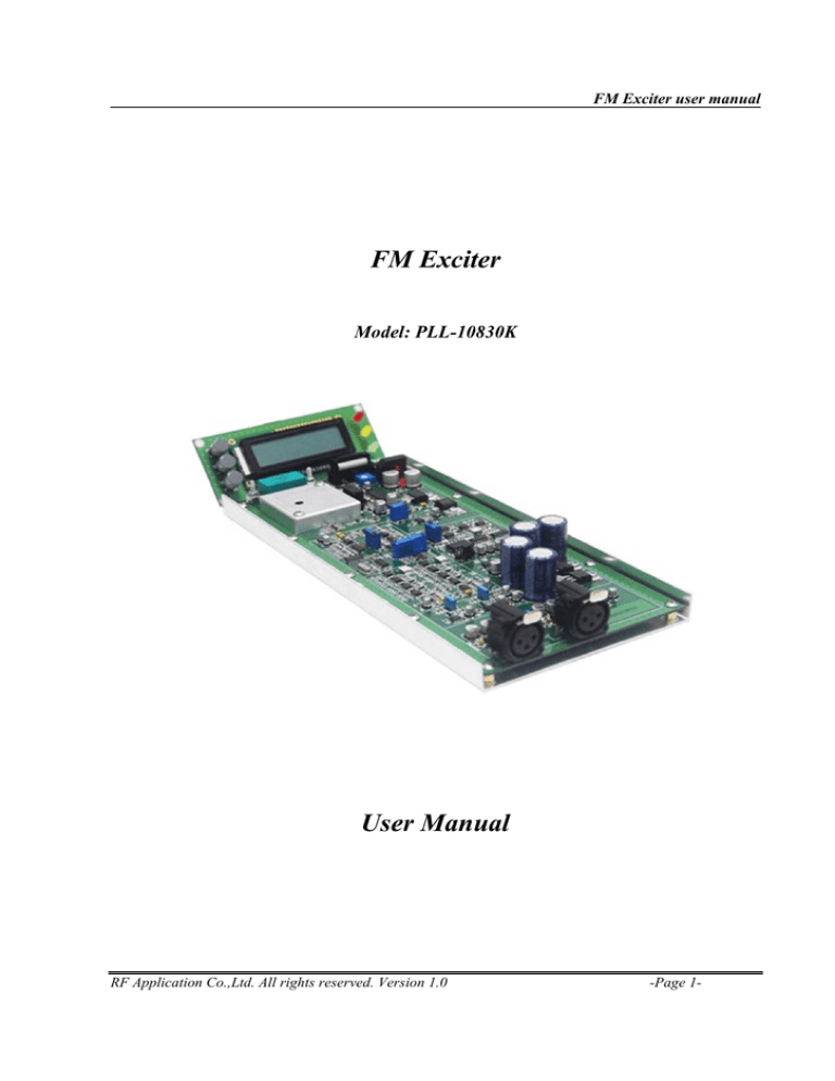
FM Exciter
Model: PLL-10830K
User Manual
RF Application Co.,Ltd. All rights reserved. Version 1.0
-Page 1-
FM Exciter user manual
CONTENTS
General Information
The PLL-10830K is the latest in a series of FM transmitter for demanding applications. It
is especially suited for repeaters, audio and data links, packet radio, and remote control. The
PLL-10830K was designed to provide a single-channel FM transmitter for transmit in the VHF
bands.
Installation Mounting
Some of support should be provided under the PC board, generally mounting the board
with 8 holds. The transmitter board relies on the mounting hardware to provide the DC and RF
output ground connections to the ground plane on the board.
Electrical Connections
Power supply should be connected to the connector on the PC board with #4 wire, which
can be extended to a connector or feed through capacitors used on the cabinet in which it is
installed. Be very careful not to route the wiring near RF components on the board, for instance
underneath the board. The exciter operates VAC or VDC from 18 – 0 – 18 to 24 – 0 – 24 to at
about 1000 mA peak with full RF output. A well-regulated power supply should be used. Be sure
that the power source does not carry high voltage or reverse polarity transients on the line, since
semiconductors in the transmitter can be damaged.
+18 V
0V
-18V
RF Application Co.,Ltd. All rights reserved. Version 1.0
-Page 2-
FM Exciter user manual
Audio Input Connections
Be sure to observe polarity! Signal. You can connect audio to this transmitter.
Right audio input signal
Left audio input signal
Connector type: XLR female
1
2
3
GND
Positive ( + )
Negative ( - )
RF Output Connections
The RF output connection should be made to the transmitter with a solder pad on
transmitter (or SMA female on request). If you want to extend the RF output connection, we
recommend using a short length of RG-316 coax with the plug and keep the pigtails very short.
RF output
Ground
RF Application Co.,Ltd. All rights reserved. Version 1.0
-Page 3-
FM Exciter user manual
LCD Connections
The LCD can display as 16x2 typical. You can connect to transmitter board.
Connect to LCD panel
LCD Panel
This is parameter display and control.
LED ON status
Up (Change parameter display
and increase frequency
Lock ON status
Down (Change parameter
display and decrease frequency
Over Modulation
status
Enter (Set to change
frequency)
Quick Specification Reference
- Operating frequency
Model: PLL -10830K 87.50 – 108.00 MHz
- RF Output: up to 0.5Watts
- Operating Power: 18 – 0 – 18 VDC at 1000 mA
- Size: 130mm. W x 270mm. D x 40mm. H
RF Application Co.,Ltd. All rights reserved. Version 1.0
-Page 4-
FM Exciter user manual
Operation
Turn on
Be sure that the power source does not carry high voltage or reverse polarity transients on
the line, since semiconductors in the transmitter can be damaged. After you turn on, The LCD can
be displayed as:
Then the LCD will displayed as:
To change the LCD displayed all parameter as:
The PLL of transmitter will tune. After the PLL is locked to the frequency, LED will be displayed on
LCD panel.
While the transmitter have audio input signal, LCD will be displayed as:
Frequency Setting
This menu lets you read and set the operating frequency.
You can modify the set frequency using the UP (the frequency increases) and DOWN (the
frequency decreases) push buttons. After having set a new frequency value, the exciter will
release from the current frequency and it will latch onto the new operating frequency.
RF Application Co.,Ltd. All rights reserved. Version 1.0
-Page 5-
FM Exciter user manual
Adjustments
Frequency correction
The frequency from VCO will oscillator as frequency setting. The frequency can be error in
the long time in use. You can adjustment to frequency correction by varicap as the picture as
below.
Frequency adjustment
correction
LCD contrast
The LCD display can adjust the contrast as picture below:
LCD contrast
Modulation input signal adjustment
You can adjust to modulation signal by potentiometer.
Modulation adjustment
RF Application Co.,Ltd. All rights reserved. Version 1.0
-Page 6-
FM Exciter user manual
Left and right input impedance
You can select to audio input impedance by resistor as below:
The factory set audio
input impedance to
10Kohm. If you need
to input impedance to
600 ohm, you will be
removed SMD
resistor 10kohm and
replace to 600 ohm
both left and right.
Audio input signal adjustment
You can adjust to audio signal by potentiometer.
Right audio input adjustment
Left audio input adjustment
RF Application Co.,Ltd. All rights reserved. Version 1.0
-Page 7-
FM Exciter user manual
TROUBLESHOOTING
General
The usual troubleshooting techniques of checking dc voltages and signal tracing with an
RF voltmeter probe, oscilloscope and spectrum analyzer will work well in troubleshooting the PLL10830K. DC voltage charts and a list of typical RF output levels are given to act as a guide to
troubleshooting. Although voltages may vary widely from set to set and under various operating
and measurement conditions, the indications may be helpful when used in a logical
troubleshooting procedure. The most common troubles in all kits are interchanged components,
cold solder joints, and solder splashes. Another common trouble is blown transistors and IC's due
to reverse polarity or power line transients. Remember if you encounter problems during initial
testing that it is easy to install parts in the wrong place. Don't take anything for granted. Double
check everything in the event of trouble.
Hum and Noise
The VCO and loop filter are very sensitive to hum and noise pickup from magnetic and
electrical sources. Some designs use a shielded compartment for VCO’s. We assume the whole
board will be installed in a shielded enclosure, so we elected to keep the size small by not using a
separate shield on the VCO. However, this means that you must use care to keep wiring away
from the VCO circuit at the right side of the board. Having the board in a metal enclosure will
shield these sensitive circuits from florescent lights and other strong sources of noise. Because
the frequency of a synthesizer basically results from a free running LC oscillator, the tank circuits
very sensitive to microphones from mechanical noise coupled to the coil. You should minimize
any sources of vibration that might be coupled to the transmitter, such as motors. Excessive noise
on the dc power supply that operates the transmitter can cause noise to modulate the synthesizer
output. Various regulators and filters in the Receiver are designed to minimize sensitivity to wiring
noise. However, in extreme cases, such as in mobile installations with alternator whine, you may
need to add extra filtering in the power line to prevent the noise from reaching the transmitter.
Other usual practices for mobile installations are recommended, such as connecting the + power
and ground return lines directly to the battery in-stead of using cigarette lighter sockets or dash
board wiring.
RF Application Co.,Ltd. All rights reserved. Version 1.0
-Page 8-
FM Exciter user manual
Quality control
The PLL-10830K are test from our lab. We guarantee to quality and reliable all products
from our factory
1. Frequency Error test ( < 500 Hz)
2. Frequency Deviation test ( +- 75 kHz (+-3%) )
RF Application Co.,Ltd. All rights reserved. Version 1.0
-Page 9-
FM Exciter user manual
3. Out of Band Emission test
RF Application Co.,Ltd. All rights reserved. Version 1.0
-Page 10-


