11557 DS L31 LNA.indd
advertisement
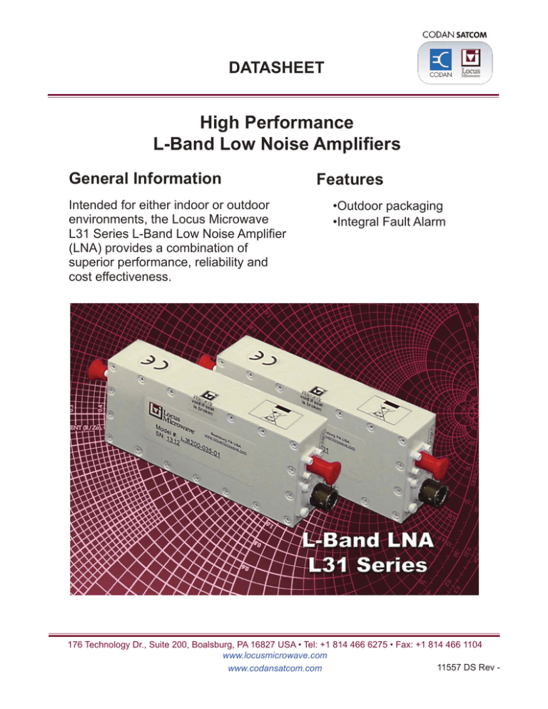
DATASHEET High Performance L-Band Low Noise Amplifiers General Information Intended for either indoor or outdoor environments, the Locus Microwave L31 Series L-Band Low Noise Amplifier (LNA) provides a combination of superior performance, reliability and cost effectiveness. Features •Outdoor packaging •Integral Fault Alarm 176 Technology Dr., Suite 200, Boalsburg, PA 16827 USA • Tel: +1 814 466 6275 • Fax: +1 814 466 1104 www.locusmicrowave.com 11557 DS Rev www.codansatcom.com L31 Series Low Noise Amplifiers Range Units Notes 1.510-1.577 or 1.525-1.561 1.500-1.700* 30, 35, 40, 45 or 50 max. 35, 40, 45 or 50 max. 50 or 60 min. +/-0.5 max. +/-1.0 max. +/-0.25 max +10, 12, 18 or 20 min. GHz GHz K K dB dB dB dB dBm 1.3 typ., 1.5 max. 1.5 typ., 2.0 max. 1.3 typ., 1.5 max. 1.5 typ., 2.0 max. 0 max. 0.1 max. :1 :1 :1 :1 dBm O /dB non-damaging @-5 dBm output 0.01 max. 0.001 max. 0.1 max. 0.5 max. ns/MHz ns/MHz2 ns p-p ns p-p per 40 MHz per 40 MHz per 40 MHz per 40 MHz +12 to +24 220 nom. VDC mA 110/220 VAC available contact closure Form ‘A’ current sensing Outline LMI Dwg #11490 inches Weight .65 lbs. Finish paint white RF Input N or SMA Female RF Output N or SMA Female 4 pin MS-type Electrical Specifications Frequency Noise Temperature 1.500-1.700 GHz* Gain Gain Flatness 1.500-1.700 GHz* Gain Slope P1dB VSWR Input 1.500-1.700 GHz* Output 1.500-1.700 GHz* Overdrive AM/PM Conversion Group Delay Linear Parabolic Ripple 1.500-1.700 GHz* Power Requirement Input Voltage Current Fault Alarm @+23OC @+23OC per full band per full band per 10 MHz Mechanical Specifications Connectors Power/Alarm mate included Environmental Operating Temperature Humidity -40 to +60 100 O C % Specifications are subject to change at the discretion of Locus Microwave, Inc. www.locusmicrowave.com www.codansatcom.com with condensation 06/11 11557 DS Rev - D C B A Outline Drawing 4 4 2.000 RF INPUT SMA FEMALE SHOWN N FEMALE AVAILABLE .500 .250 3 PRODUCT LABEL LOCATION .500 3 Locus Microwave, Inc. 4.500 3.500 --- ZONE - REV 2 CHANGE NO INITIAL RELEASE REVISION HISTORY DECIMALS .XX ± .01 .XXX ± .005 THIRD ANGLE PROJECTION ± 0°-30' ANGLES FRACTIONS ± 1/64" UNLESS OTHERWISE SPECIFIED DIMENSIONS ARE IN INCHES TOLERANCES DESCRIPTION Pin A: +Vdc Pin B: Gnd Pin C: Common Pin D: Closed on Fault DC POWER/ALARM MS3112E8-4P RF OUTPUT SMA FEMALE SHOWN N FEMALE AVAILABLE 1.000 2-56 UNC-2B x .188" DEEP 4 PLACES THIS SIDE ONLY 2 SES APPR BY 11/02/25 DATE 1 SES DWN BY CODE IDENT 11490 DWG NO. - PAGE 1 OF 1 OUTLINE, L-BAND LNA 34TH3 REV LOCUS MICROWAVE INC. B SIZE SCALE 1 : 1 PROJ : 1 D C B A L31 Series Low Noise Amplifiers Model Number Configuration 1 2 34 5 6 7 L31xxxx-xxx-xx 1 Frequency 0 = 1.510-1.577 GHz 2 Gain 5 = 50 dB 6 = 60 dB 1 =1.525-1.561 GHz 2 = 1.500-1.700 x GHz *1 3 P 1dB 1 = 10 dBm 4 2 = 12 dBm Power D = 12-24 VDC 5 A = 110/220 VAC Noise Temperature 030 K 035 K 4 = 18 dBm 040 K 5 = 20 dBm 045 K 050 K 6 Input Type 7 Output Type S = SMA (Female) N = N (Female) S = SMA xxxx(Female)*2 N = N (Female) A Accessories B Finish Federal Standard 0 = None 0 = White 37925 1 = 4 Pin Mate DC Only 1 = Dark Green 34094 2 = Desert Tan 33446 3 = Beige 37722 4 = Sand 33303 5 = Forest Green 34083 2= 4 Pin Pigtail DC Only 3= 6 Pin Mate AC Only 4= 6 Pin Pigtail AC Only 6 = Metalast *1 NOTE: 35K NOISE TEMP MINIMUM *2 NOTE: LNAs ordered as components of a Redundancy system xx require an SMA (F) output connector. Example: 1.525-1.561 GHz, 50 dB Gain, +10 dBm P1dB , DC Power, 45K Noise L 3 1 1 5 1 D - 045 - N N Frequency Noise Temperature Gain Output Type Input Type Power P1dB Note: Selections shaded in gray will require Engineering review. Please confirm configurations against product specifications, and with factory, prior to order. www.locusmicrowave.com www.codansatcom.com 11557 DS Rev -
