BlueRidge
Technologies
www.BRTint.com : 800-241-9173 Blue Ridge Technologies®
Occupancy Sensor
© 2012 Blue Ridge Technologies International, LLC All Rights Reserved. BR-OCC-IG-V11.00
Install Guide : Page 1
Hardware Connection Instructions
Attention
This section serves as a notice of the immediate or potential dangers involved when working with the equipment described throughout this manual. Any
person involved in installation, maintenance, or service of the equipment should first carefully examine the equipment and read the instructions contained
in this manual to ensure that personal and/or equipment injury is avoided.
The following safety messages appear throughout this manual to alert of immediate or potential danger to life as well as property.
Note : Indicates an important note.
Tip : Indicates a helpful tip or trick.
Safety Reminder : Applicable safety instructions will be included with this symbol.
DANGER : Indicates an immediately hazardous situation which ,if not avoided, will result in serious injury or death.
WARNING : Indicates a potentially hazardous situation which ,if not avoided, may result in serious injury or death.
CAUTION : Indicates a potentially hazardous situation which ,if not avoided, may result in minor or moderate injury.
Disclaimer
This equipment has been tested and found to comply with the limits for a Class A digital device, pursuant to part 15 of the FCC Rules. These limits are
designated to provide reasonable protection against harmful interference when the equipment is operated in a commercial environment. This equipment
generates, uses, and can radiate radio frequency energy and, if not installed and used in accordance with the instruction manual, may cause harmful
interference to radio communications. Operation of this equipment in a residential area is likely to cause harmful interference, in which case the user will
be required to correct the interference at his own expense.
Instructions contained in this user’s guide should be performed only by qualified persons in accordance with local and national codes. Blue Ridge
Technologies International, LLC and its affiliates assume no responsibility for any consequences related to the improper use of this manual.
Common (Brown)
G
Power (Red)
Ground (Black)
Controller
OCC
+24V
GND
G
OCC Lead
Satellite / Zone Control
OCC Lead
24V GND
24VDC Supply
SC / ZC Terminations (Relay)
Occupancy Sensor
UI-1
GND
+24V
BlueRidge
Technologies
www.BRTint.com : 800-241-9173 Blue Ridge Technologies®
© 2012 Blue Ridge Technologies International, LLC All Rights
Reserved.
BR-OCC-IG-V11.00
Satellite
/ Zone
Control
N/
Grou
Comm
Po
OCC Lead
Install Guide : Page 2
SC / ZC Terminations (Relay Externally Powered)
Document Overview
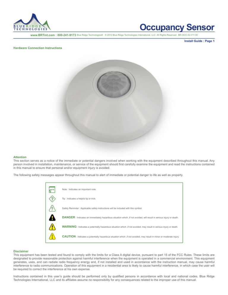
This document provides connection instructions for the following Blue Ridge Technologies Occupancy Sensor (OCC) products :
Hallway Occupancy Sensor, Passive IR
UI-1
Ceiling Mount Occupancy Sensor, Passive IR / Passive Dual Technology
+24V
Corner / Wall Mount Occupancy Sensor, Passive IR / Passive Dual Technology
Satellite / Zone Control
Ceiling Mount Bracket
These OCC models are compatible with Retrofit Interior (RI), Retrofit Kit (RK), Relay Panel (RP), Satellite Control (SC), and Zone Control (ZC).
24V GND
For OCC software configuration refer to the Application Guide.
24VDC Supply
Additional third party documentation is included for detailed specifications and instructions.
Identification
Ceiling Mount Sensor
Hallway and Corner/Wall Mount Sensor
N/
Comm
Pow
Grou
OCC Lead
Ceiling Mount Bracket
(Figure 1)
Connection
Electrical Specifications
Power Input / Draw: 24VDC / 16mA
Leads: 7.00”(178mm)L, 6-wire
Red: 24VDC
Black: Ground
White: Signal
Grey: N/O (relay)
Brown: Common (relay)
Blue and/or Violet: Unused
RK / RI / RP Digital Input:
Jumper Configuration: 8 input segments, dry contact (N)
Wire Requirement / Maximum Length: 18AWG (Solid or Stranded) / Dry Contact 500’(152m)
SC / ZC Universal Input:
Wire Requirement / Maximum Length: 18AWG (Solid or Stranded) / 500’(152m)
RI / RK / RP Controller Terminations (Dry Contact)
1
G
SC / ZC Terminations (Standard)
N/O (Grey)
Common (Brown)
Power (Red)
Ground (Black)
Controller
OCC
Signal (White)
UI-1
+24V
GND
Power (Red)
Ground (Black)
OCC Lead
Satellite / Zone Control
OCC Lead
24V GND
24VDC Supply
OCC
SC / ZC Terminations (Relay)
UI-1
GND
+24V
N/O (Grey)
Ground (Black)
Common (Brown)
OCC
Power (Red)
Satellite / Zone Control
OCC Lead
SC / ZC Terminations (Relay Externally Powered)
N/O (Grey)
UI-1
+24V
Common (Brown)
Power (Red)
Ground (Black)
Satellite / Zone Control
Disconnect power before performing OCC installation.
All circuits must be tested for wiring errors and shorts prior to OCC installation.
Ceiling Mount Sensor
Hallway and Corner/Wall Mount Sensor
Ceiling Mount Bracket
24V GND
24VDC Supply
OCC
OCC Lead
(Figure 2)


