3.4(1)
MULTISIM DEMO 3.4: MAXIMUM POWER TRANSFER
Are you the sort of person who needs to actually see that the most power is transferred to a load
resistor when it is equal to the source resistor? Or do you just believe what is told to you? In
the next section, we’re going to show that the most power is indeed transferred when the load
resistance, RL, is matched to the source resistance, RS.
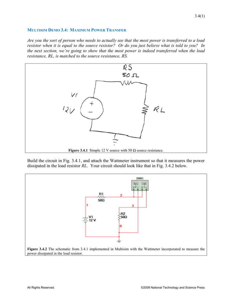
Figure 3.4.1 Simple 12 V source with 50 Ω source resistance.
Build the circuit in Fig. 3.4.1, and attach the Wattmeter instrument so that it measures the power
dissipated in the load resistor RL. Your circuit should look like that in Fig. 3.4.2 below.
Figure 3.4.2 The schematic from 3.4.1 implemented in Multisim with the Wattmeter incorporated to measure the
power dissipated in the load resistor.
All Rights Reserved.
©2009 National Technology and Science Press
3.4(2)
For this Exercise, R1 and R2 are not good names, so we will want to change them to the names
found in the Fig. 3.4.1 of RS and RL, respectively. To do this:
1. Double-click on R1 to bring up the properties window
2. Click on the Label tab
3. Under the “RefDes” field enter “RL” as shown in Fig. 3.4.3.
4. Click OK
Do the same thing for R2, except redefine it as RS. Also, while you’re at it, redefine the voltage
source V1 to be VS in order to correspond with the name on the schematic. The same basic
naming procedure applies. When all of this is done your circuit should look like Fig. 3.4.4.
Figure 3.4.3 Properties window of the Resistor R1 being redefined as “RL”.
Figure 3.4.4 The circuit with new component labels.
All Rights Reserved.
©2009 National Technology and Science Press
3.4(3)
Now that all of this renaming of components is out of the way, let’s get down to simulating the
circuit. As the circuit stands, RS = RL, which from circuit theory means that the most possible
button or
power should be transferred to RL. Start the simulation by pressing either the
pressing F5 to see what power is dissipated in RL. Your result should match that in Figure 3.4.5.
Figure 3.4.5 Power dissipated in RL when load is matched to source.
Now let’s change the value of RL to see what the power is when RL ≠ RS. Stop the simulation,
set RL to 40Ω, and then re-run the simulation. Your result should appear like that in Fig. 3.4.6
below.
Figure 3.4.6 Power dissipated in RL when the load resistance is 40 Ω.
All Rights Reserved.
©2009 National Technology and Science Press
3.4(4)
As we can see on the previous page in Fig. 3.4.6, the power dissipated in the load is less than it is
when it is matched to the source resistance (RS = RL). What if we increase the resistance to
some ridiculous amount like 1 kΩ? Try it. You should get something that resembles what is
shown in Fig. 3.4.7.
Figure 3.4.7 Power dissipated in RL when the load resistance is 1 kΩ
Go ahead and change the resistance of RL to any value you can think of. No matter what, the
power dissipated will never be as great as it is when RL = 50 Ω. Any load resistor value other
than 50Ω will provide less than ideal power transfer. This concept is investigated graphically in
the next section.
All Rights Reserved.
©2009 National Technology and Science Press


