FT1390-2-9-500
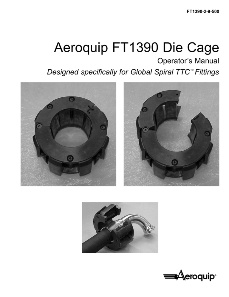
Aeroquip FT1390 Die Cage
Operator’s Manual
Designed specifically for Global Spiral TTC™ Fittings
Designed specifically for Aeroquip’s Global Spiral TTC™ fittings, the FT1390 Die Cage simplifies
the crimping process. The hinged design allows for clearance of large elbow fittings, while the
latchable one-piece construction makes for easy handling.
Features
Benefits
•
•
•
•
•
•
•
•
•
•
Hinges open
Uses FT1209 dies
Chrome moly alloy steel
Simple latch mechanism
Ion nitrided wear surfaces
Allows clearance of Global Spiral TTC™ elbows
Ability to convert FT1209 die cage
Maximum durability/high strength
Easy handling
Maximum service life
Ordering Instructions
Complete Die Cage Assemblies
FT1390-200-14
FT1390-200-15
FT1390-200-16
FT1390-200-20
FT1390-200-21
FT1390-200-23
2
Die Cage Repair Kit
(Complete cage, less dies)
FT1390-2-9
Note: For individual die cage components,
please refer to page 7 of this bulletin.
The FT1390 Die Cage can be used with the
following Aeroquip Crimp Machines.
ProCrimp 1390
FT1340
FT1307
FT1360
FT1209
3
FT1390 Die Cage Operation
Latch Operation
The FT1390 die cage uses a simple spring mechanism to keep the latch in place. To latch or
unlatch the cage, simply push the backside of the latch to compress the spring. Adjust the latch to
the appropriate position. (See below)
Latched
Unlatched
Fitting Assembly
Please refer to the JA55 Crimp Specifications Manual or the appropriate bulletin for the proper
hose/fitting combinations, skive preparation, crimp diameters, crimp ovality, crimp length and
proper die selection.
Assembly of Straight Fittings
Straight fittings do not require the hinged feature of the FT1390 Die Cage and should be assembled as follows:
1. Prior to handling, verify that the cage is latched.
2. Install the die cage into the crimp machine by placing the “T-nut” into the slot on the pressure
plate.
3. Insert the fitting.
4. Position the fitting and crimp.
4
Assembly of Elbow Fittings
1. Prior to handling, verify that the cage is latched.
2. Install the die cage into the crimp machine by placing the t-nut into the slot on the pressure
plate.
3. Unlatch the die cage.
4. Open the die cage by pulling up on the top (2) dies. Rest the t-nut on top of the pressure plate.
(see Figure A and B)
Figure A
Figure B
5. Insert the fitting. If the fitting is successfully inserted, proceed to step 8. If the fitting will not clear
the opening, close the die cage and advance the machine approximately 1/2". (see Figure C
and D)
Figure C
Figure D
6. Re-open the die cage.
7. Insert the fitting.
8. Close the die cage. Latching the die cage is not necessary during the crimping process.
9. Position the fitting and crimp.
10. When removing the fitting, the user may want to open the die cage for additional clearance.
5
FT1390 Die Cage Maintenance
For maximum service life, die cages need to be lubricated and kept clean from dirt and debris.
Sliding surfaces of the individual dies are the areas of most concern. Use NEVER-SEEZ
(Aeroquip Part Number FT1092) for all die cage lubrication.
Exposed Die Surfaces and Crimp Ring
• Lubricate the angled die surfaces every 20 crimps. The style of hose and fittings crimped with
the FT1390 die cage produce higher loads on the die cage and crimp machine, which requires
lubrication at short intervals.
• Remove old grease and lubricate every 200 crimps. NEVER-SEEZ will build up on the sides
of the dies and in the crimp ring during the crimping process. This residue will become contaminated with metal and plating chips and airborne contaminants, which can cause premature wear
of the dies and crimp ring.
• The flat surfaces of the dies, that protrude beyond the backplate, should be lubricated every
200 crimps.
• Every 500 crimps, inspect the contact area of the dies and crimp machine. The surfaces should
be smooth with no galling. Components with galled surfaces need to be replaced.
Concealed Die Surfaces and Die Cage Components
Every six months or 1000 crimps, which ever occurs first, disassemble the die cages for
inspection and lubrication of parts. See page 7 for parts breakdown.
• The sliding surfaces between the dies and front/back plates should appear smooth with no
galling. Galled components need to be replaced.
• Replace springs that show signs of damage or collapse, such as those which are shorter than
others.
• Inspect remaining components of the die cage and replace those that show significant wear.
6
FT1390 Die Cage Parts Breakdown
2
4
11
9
10
6
7
7
13
8
Detail
1
2
3
4
5
6
7
8
9
10
11
12
13
5
12
3
Qty
1 pc
1 pc
1 pc
1 pc
4 pc
1 pc
1 pc
3 pc
1 pc
8 pc
1 pc
8 pc
8 pc
1
Part Number
FT1390-2-9-1
FT1390-2-9-2
FT1390-2-9-3
FT1390-2-9-4
FT1390-2-9-5
FT1390-2-9-6
FT1390-2-9-7
FT1209-2-9-1
FT1209-2-9-5
FT1209-2-9-7
FT1209-2-9-8
21057-7
FT1209-200-SIZE
Description
Back Plate (lower)
Back Plate (upper)
Front Plate (lower)
Front Plate (upper)
Spacer
Shoulder Screw (long)
Latch Assembly
BHCS 5/16-18 x 3.90 long
Shoulder Screw (short)
Spring
BHCS 5/16-18 x 3.50 long
Roll Pin .25 dia. x .62 long
Dies
7
Eaton Aeroquip
Industrial Division
3000 Strayer Road, P.O. Box 631
Maumee, Ohio 43537-0631
419/867-2600, Fax: 419/867-2629
www.aeroquip.com
MET0-4031
2.5M
9/00
Specifications subject to change without notice
FT1390-2-9-500
©2000 Eaton Aeroquip, All Rights Reserved


