Understanding the R-R Test
advertisement

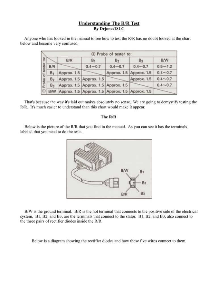
Understanding The R/R Test By Drjones18LC Anyone who has looked in the manual to see how to test the R/R has no doubt looked at the chart below and become very confused. That's because the way it's laid out makes absolutely no sense. We are going to demystify testing the R/R. It's much easier to understand than this chart would make it appear. The R/R Below is the picture of the R/R that you find in the manual. As you can see it has the terminals labeled that you need to do the tests. B/W is the ground terminal. B/R is the hot terminal that connects to the positive side of the electrical system. B1, B2, and B3, are the terminals that connect to the stator. B1, B2, and B3, also connect to the three pairs of rectifier diodes inside the R/R. Below is a diagram showing the rectifier diodes and how these five wires connect to them. The top rectifier diodes are the Positive rectifier diodes and the bottom set are the Negative rectifier diodes. B1, B2, and B3, each connect to a pair consisting of one positive and one negative rectifier diode. How A Rectifier Diode Works A rectifier diode is a one-way electronic valve. The cathode is the negative end, and the anode is the positive end. When the anode is approximately .7 volts more positive than the cathode the diode “turns on” and electrons will flow from the cathode end, through the diode, and emerge at the anode. Electrons do not (should not) flow from anode to cathode. Below is a diagram showing a diode with the cathode and anode marked. The meters and probes show how you would measure a diode along with the readings you would expect to see with your meter set to the diode test setting. As you can see the meter on the top has the probes in the right orientation to forward bias, or “turn on” the diode. The positive probe is at the positive end of the diode and the negative probe is at the negative end of the diode. The meter below has the probes reversed and gives no reading. If you measured a diode with the probes as they are in the bottom meter and got a reading of anything other than zero* the diode would be bad. *Note: Some meters will register zero (no reading) in a different way. It may show a dash, or a 1., or OL, etc. You must know how your meter indicates zero. Let's take another look at the R/R diagram. Notice that the B/R (positive) wire is connected to the cathodes (negative end) of the positive rectifier diodes, and the B/W (ground) wire is connected to the anodes (positive end) of the negative rectifier diodes. (for more about why this is you can read “How The LC-C90 Charging System Operates” but it isn't needed for this article) Scroll down to the next page Testing Below is a much easier chart to follow. Let's test the positive diodes first. With your meter set to the diode setting place the negative probe on the B/R terminal. Touch the positive probe to B1, B2, and B3, one at a time. This will test each of the positive diodes in the diagram from left to right. You should get a reading of .4 - .7 on your meter for each of the three positive diodes. Anything outside these numbers indicates a bad diode, and therefore a bad R/R. Now put the positive probe on the B/R terminal and place the negative probe on B1, B2, and B3. Your meter should read zero for all three positive diodes. If any one of them reads anything other than zero that rectifier diode would be bad and the R/R is shot. If all is good continue on to the negative rectifier diodes. To test the negative rectifier diodes you put the positive probe on the B/W terminal, and use the negative probe to again check B1, B2, and B3. Each diode should read between .4 - .7 on the meter. Again, anything outside these numbers indicates a bad diode, and therefore a bad R/R. Now put the negative probe on the B/W terminal, and again use the positive probe at B1, B2, and B3. You should read zero on the meter. Anything other than zero indicates a bad negative rectifier diode and therefore a bad R/R. Congrats! You've just tested your R/R. Hey...That Was Simple! All Is Well With My R/R...Right? One the face of it...yes. If your R/R passed the above checks you could conclude that it's good. Unfortunately though it isn't a conclusive test. It's just the only actual test you can do. All the test is really telling you is there aren't any obviously bad diodes. If one diode conducted in both directions, or if one didn't conduct in either direction, you would know for certain that the R/R was bad. Unfortunately it doesn't mean a diode isn't “leaky” while it's doing it's work. A diode is a semiconductor. You can think of it as an “active” component. It has the ability to turn on and off. When it gets hot it can become sort of stuck and not fully turn off. This is what we call “leaky”. If diodes gets leaky they can cause stator damage. What basically happens is the leaky diode can allow a stator phase to carry voltage and current constantly, and that means it's dissipating power constantly. In normal use, each phase of the stator alternates between working and not working which means they aren't constantly dissipating power. Constant power means constant heat, and consistent heat is a recipe for a possible stator failure. Does that mean every time a stator fails you need to replace the R/R as a preventative measure? There really isn't any clear cut answer to that question. Generally speaking, R/R's are pretty reliable devices. They are also a bit pricey so it's not something like a spark plug that you might as well replace since it's only a couple of bucks. I'll give you some things to consider. If you're looking into a charging problem and you've ruled out connection problems, (there are a lot of connections) and the stator tests good, and the battery appears to be good, (this is not easily determined in a lot of cases because if the battery isn't 100% it can make it seem like there is a charging system problem) then the R/R might seem the most likely culprit. Change it only as a last resort. Batteries become weak much more often than R/R's go bad. If the R/R tests good I would absolutely swap the battery out before I would change an R/R. If your stator tests bad and you find it is burnt in a very localized area the R/R most likely had nothing to do with this. In this case I would leave the R/R alone...but that is an absolute judgment call. If you look at the stator and it is burnt on the majority of the coils that to me makes the R/R suspect. It would appear that at least one phase is constantly dissipating power. That to me would justify spending the cash on a new R/R. If you are replacing a stator (which is also a pricey item itself) you may think it's (not so) cheap insurance to replace the R/R as well. After all, you won't find out the R/R might have been faulty until you burn out the next stator in a relatively short amount of time. Now you'd be spending the money for two stators plus the new R/R. I wish I could give you better criteria to go by...but it is what it is. There really isn't any definitive way to tell if you have an R/R that may be failing only while hot and under a load. It's an educated guess at best. It's your bike and your wallet, so it's your call. Ride Safe!


