Tuner Topics
Harold C. Ritchey, Advanced Energy Industries, Inc.
Understanding the dynamics of your matching network can ensure that you have an efficient, dependable process design and a well-integrated blueprint for long-term processing success.
Although simple in component
design, tuners can create or solve
significant problems in plasma
processes. Placement and connections
dramatically affect RF power supply
performance, process efficiencies,
and safety. In fact, improperly
installed tuners are a frequent cause
• Change in cable attenuation with time
(typically 0.1 dB per 100' per 60 days
at high humidity)
• Changes with time in the
instrumentation following the detectors
• Reading accuracy of analog meters
(typically 3% for meters without
mirrored scale)
This discussion will examine the
design implications of these factors,
typical tuner configurations,
the tuner-chamber relationship
and calibration, common system
errors, and adjustments for optimal
performance.
of system damage and downtime.
One common misconception is that
Description
the RF power readings at the tuner
A tuner is an electromechanical apparatus that transforms an electrical load
should correspond to the RF power
impedance of R ±jX at the chamber to a constant R at the output of the generator.
readings at the generator. This is
The input value of R conforms to the characteristic impedance of coaxial
rarely the case—readings are rarely
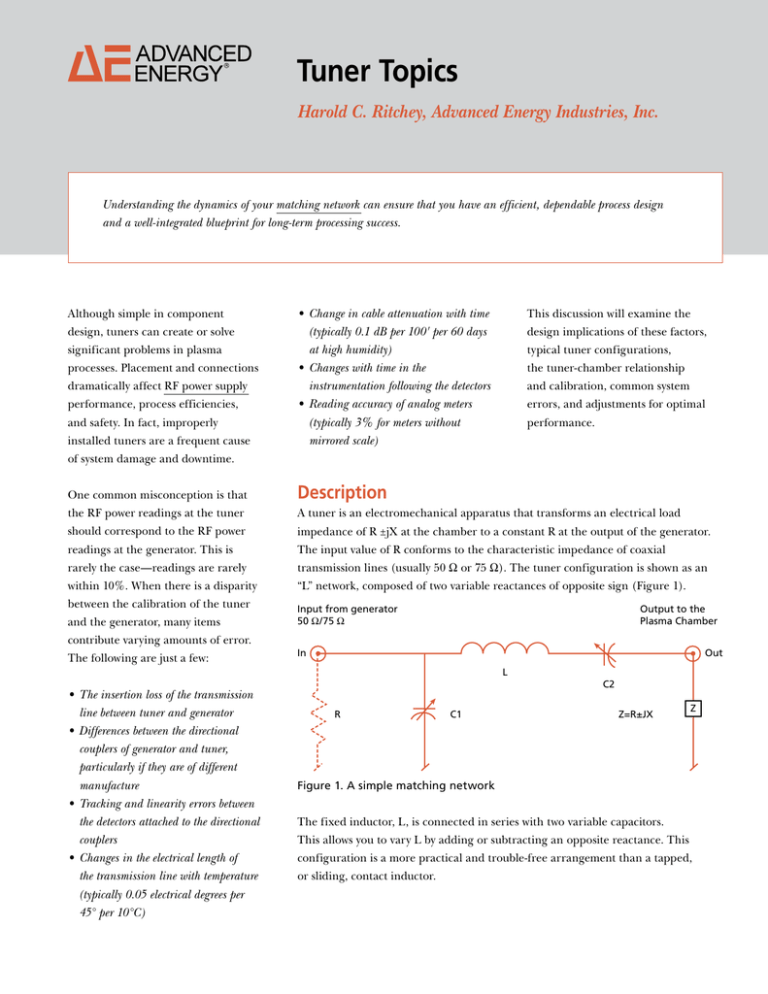
transmission lines (usually 50 Ω or 75 Ω). The tuner configuration is shown as an
within 10%. When there is a disparity
“L” network, composed of two variable reactances of opposite sign (Figure 1).
between the calibration of the tuner
and the generator, many items
contribute varying amounts of error.
The following are just a few:
Input from generator
50 Ω/75 Ω
Output to the
Plasma Chamber
In
Out
L
• The insertion loss of the transmission
line between tuner and generator
• Differences between the directional
couplers of generator and tuner,
particularly if they are of different
manufacture
• Tracking and linearity errors between
the detectors attached to the directional
couplers
• Changes in the electrical length of the transmission line with temperature
(typically 0.05 electrical degrees per 45° per 10°C)
R
C1
C2
Z=R±JX
Z
Figure 1. A simple matching network
The fixed inductor, L, is connected in series with two variable capacitors.
This allows you to vary L by adding or subtracting an opposite reactance. This
configuration is a more practical and trouble-free arrangement than a tapped,
or sliding, contact inductor.
advanc ed
e n erg y
The components that compose the
Tuners vary considerably from one
Placement
basic arrangement of a manually
manufacturer to another, and the
The tuner is bolted to the chamber
adjusted tuner include the L network
more spartan equipment probably
directly over the vacuum feedthrough,
with a compatible coaxial RF fitting
will not include RF power indicators
minimizing leads to the electrodes.
at the input; stout, well-insulated
or the position of reactances.
output terminals (usually threaded);
Lead Surface Area
and control knobs and shafts for
The leads must be appropriate for
C1 and C2 (well-insulated for C2),
Installation
mounted together in a suitable
Proper installation of the tuner
handled.
aluminum enclosure.
is vital to the successful operation
Use silver-plated copper strap (not
the power level and frequency to be
of the plasma chamber. A poorly
braid), 3" minimum width, 12"
For greater flexibility, servo drives
installed tuner can undermine power
maximum length. Separately insulated
for C1 and C2 may be added. The
efficiency, cause over-heating of
straps are used for the “hot” lead and
servo amplifiers are driven by
tuner components and connections,
the ground leads. This minimizes lead
analog signals derived from phase
disable tuner functions, and cause
inductance and 12R losses.
and magnitude detectors. This
stray RF fields (which can get into
configuration, too, is contained in a
the instrumentation) and other
Connections
suitable enclosure with appropriate
serious problems.
Bolted connections equipped with
connectors, manual switches for pre-
silver-plated brass washers keep
setting the tuning elements (auto/
Figure 2 illustrates an optimal tuner-
manual, forward/reverse), capacitor
to-chamber installation. Note the four
position indicators, and appropriate
factors highlighted below.
forward/reverse power indicators.
contact resistance to a minimum.
Output Cable Attenuation
Coaxial cable can be used successfully
from the tuner output to the plasma
chamber, after taking certain
precautions.
2
w h i t e
p a per
Aluminium Tuner Enclosure
Input Coax Fitting
L
A
Tuner Enclusure Bolted
to Top Chamber Plate
C2
C1
Silver-Plated Copper Strap
Leads to Top Chamber Plate
R
B
Upper Electrode Insulator
Top Chamber Plate
Chamber Wall
Top Electrode
Bottom Electrode
C
Bottom Chamber Plate
Points A, B, & C Must Be Properly
Strapped for Grounding
Figure 2. Tuner-to-chamber installation (tuner is mounted directly to the top plate of the chamber)
3
advanc ed
e n erg y
Coaxial Cable
Attenuation
If you must use coaxial cable, be
aware that serious problems can occur
if inadequate cable surface area is
provided or if lead lengths are not
A plasma load of 5 Ω using a 6' length of RG-8/U cable has a VSWR of 10 to 1
and initial and final values of attenuation equal to:
A=0.007 dBx6'=0.042 dB
101
=0.212 dB
Aa=0.042 dB
20
[
minimized. In fact, this is the most
common cause of load-matching
]
If the input power were 1000 W to the matched line, the power loss would be:
problems.
For example, the attenuation of RG-
dB=10 log
8/U(RG-393) coaxial cable is 0.7 dB
per hundred feet at 13.56 MHz. This
is the attenuation of the cable when it
terminates into a 50 Ω resistive load.
The attenuation will increase when
Po
Po
= –0.042; then log
=–0.0042
Pi
Pi
Po
=10 –0.0042 = 0.9904; Po=990.4
Pi
Power loss=Pi - Po=9.6 W
the line terminates into a load other
than 50 Ω. The increased attenuation
For the same input and a VSWR of 10 to 1, the attenuation is now 0.212 dB,
is given by:
and power loss is:
Aa=A
[
ρ2+1
2ρ
]
Where:
A=Initial attenuation
Aa=Final corrected value of
attenuation
dB=10 log
Po
Po
=–0.212; then log
=–0.0212
Pi
Pi
Po
=10 –0.0212 = 0.952; Po=952
Pi
Power loss=Pi - Po=48 W
ρ=VSWR
These power losses can cause unpredictable changes in system power calibration
and clearly illustrate the problems caused by the wrong cable.
Now, consider type RG-220/U. Its loss per hundred feet is 0.17 dB, about one-fourth
the loss of RG-8/U. A second alternative is to use two pieces of cable in parallel.
This gives a dual advantage: 1) the power loss will be halved, and 2) since the cable
Zo will be 25 Ω instead of 50 Ω, the loss due to VSWR also will be halved.
4
w h i t e
Tuner-Chamber Relationships
p a per
The only purpose of the tuner is to transform the chamber impedance of
Impedance of the
Plasma Chamber
R ±jX into a constant 50 Ω or 75 Ω of pure resistance. This allows the generator
The impedance of the plasma chamber
and transmission line to operate at maximum efficiency. Remember that tuner
will vary widely depending upon
calibration need not precisely coincide with generator calibration. The tuner
plate area, plate spacing, gas type
power indicators simply are there to display whether the tuner is "at tune"
and pressure, temperature, and other
(minimum reflected power) or not.
parameters. Typically, the impedance
consists of resistance and capacitive
The chamber impedance before ionization is capacitive. The value of capacity is
reactance, with R values from a few
readily calculated by measuring the area and spacing of the electrodes and referring
ohms to tens of ohms, and Xc from
to the dielectric constant of the gas at chamber pressure. The reactance then can be
tens of ohms to hundreds of ohms.
calculated at the frequency in use.
The RF current into the plasma
The imaginary portion of the chamber impedance is expressed as:
1
XC =
2πƒC
chamber with low Z values and power
in the kilowatt range can reach sizable
values. Since the RF skin effect at
13.56 MHz is about 0.7 mil, adequate
surface area should be provided by
Since the gas is not ionized, it has high resistivity and makes part of the chamber
using multiple strap leads.
impedance under this condition very high. The chamber voltage, E, will be equal
to P(Xc), where P equals forward power of the generator at the chamber, not at
the generator. (This is due to the additional line loss caused by the mismatched
condition. See Coaxial Cable Attenuation on page 4.)
When power is applied, the tuner servos will run, attempting to match, or
transform, the capacitive reactance to a real (resistive) input impedance. The tuner,
however, cannot transform a pure reactance into a resistance. Therefore, it will run
or "search" until the chamber ignites, or the tuner runs into the end of its range.
Depending upon the design of the tuner, it will either: 1) reverse its direction of
tuning or 2) remain against its limit switches or stops. Condition 1 is preferred.
When the chamber won't light, there may be a very elementary problem: the voltage
at the plates is less than the striking voltage of the gas type in use.
The solution is equally elementary. Calculate the chamber impedance (reactance).
Measure the forward power at the chamber. Calculate the chamber voltage, E=
P(Xc). Refer to a table of striking voltage versus gas type and pressure. Then,
you will be ready to take corrective action as necessary, i.e., increase gas pressure,
increase power, reduce losses, etc.
5
advanc ed
e n erg y
Transmission Line Transformation of Chamber
Impedances
Consider the equation below, which reveals that the input impedance to
a transmission line is a function of its length, its characteristic impedance, and
the impedance of the load when the load is not a pure resistance equal to the
characteristic impedance.
ZIN =
[
ZR + jZO tan βL
ZO + jZR tan βL
]
Where:
ZIN=Input impedance
ZO=Characteristic impedance of the line
ZR=Load impedance
βL=Line length in electrical degrees
2π
i.e., βL= ; where λ is the wavelength in the line, including its velocity factor,
λ
or the line length in degrees per meter of length
tanβL=The tangent of βL
These equations show that impedance presented to the tuner will be different from
chamber impedance and can be of opposite reactance as compared to the actual
chamber reactance (usually capacitive). The end result is that the tuner may not be
able to transform the new value of Z into a flat 50 Ω. Thus, the value(s) of L and C
in the tuner will have to be modified.
If you must use coaxial cable, keep the length to 3' or less so that tanβL will not
greatly modify the impedance from chamber to tuner. Using parallel connected
coaxial cables, such as two 50 Ω pieces, will reduce ZO in the equation to 25 Ω,
further reducing the excursion of ZIN.
Chamber Calibration
The plasma chamber is a reactive electrical load. As such, the chamber can
produce electrical and sometimes visible oscillations. These oscillations can
interfere with the "normal" operation of the chamber, the generator, the tuner,
and the instrumentation. There are several methods that can be employed to detect
the presence of chamber oscillations. The best method is to use a dual-directional
coupler and a spectrum analyzer (Figure 3).
6
w h i t e
Input Coax Cable Fitting
p a per
Coax Fitting
Coax Elbow
Coax Cable RG-22/U 3 Feet or Less
Silver-Plated Strap Leads
DC
RFL
FWD
Analyzer
Top Chamber Plate
PS
Top Electrode
Upper Electrode Insulator
Figure 3. Chamber installation (using coaxial cable from tuner output
to chamber plates) and calibration
The coupling ratio and directivity of both ports of the coupler must be known or
calibrated. Insert the coupler in the transmission line between the generator and
the tuner. Observe the analyzer display with the analyzer adjusted to display the
fundamental generator frequency to a full raster. Set the generator in the cw mode.
Now record the frequency and amplitude of all signals observed over the frequency
scan bandwidth of interest.
Repeat the same steps with the analyzer connected to the reflected port. An
oscilloscopic camera can be of great assistance in these measurements. Now sort
the displayed data as follows:
1.Identify any frequency that is an exact multiple of the fundamental and label it by its harmonic number.
2.Identify and label any frequency that is not an exact multiple of the fundamental.
3.Identify and label any frequency that lies close to the fundamental, such as 1 kHz, 10 kHz, etc.
4.Operate the generator into a dummy load, and scan the forward port of the coupler.
Identify and label all visible signals.
5.Compare all power signals obtained in step 4 with 1, 2, and 3 forward and reflected
power ratings. Remove all signals that match from the data bank.
6.Any signals in steps 2 or 3 that do not match in frequency with step 4 are now suspected
of being chamber generated. To confirm this, measure the amplitude of the suspected
signal at the forward and reflected ports of the coupler. A chamber-generated signal will be of higher amplitude on the reflected port as compared to the forward port by the directivity of the coupler at that frequency.
7
advanc ed
e n erg y
Operator Troubleshooting
Some operational problems have simple solutions. If your system exhibits any
of the specific symptoms below, try the actions recommended here.
Symptom
Action
Power won't come on.
Check fuses, RF grounds, and input
power connection.
Check output power connection and system
System won’t reduce reflected
power below 10% of forward power. grounds. Load impedance may be beyond
design limits. Check the tuner.
System exhibits sharp over-shoots
and oscillations around minimum
reflected power.
Check system grounds and RF output
connections.
The matching network cannot
be tuned in one direction.
Larger or smaller series inductance may
be required.
Cable or connectors between
tuner and chamber are hot.
Check RF grounds. Lower the impedance
between the tuner and the chamber. Move
tuner closer. Use leads and conductors with a
greater surface area or types that can better
handle the power level and frequency.
To view AE®’s portfolio of matching networks and RF power supplies, visit:
www.advanced-energy.com/en/RF.html
To view AE®’s complete product portfolio, visit:
www.advanced-energy.com/en/products.html
Specifications are subject to change without notice.
Advanced Energy Industries, Inc. • 1625 Sharp Point Drive • Fort Collins, Colorado 80525
T: 800.446.9167 or 970.221.4670 • F: 970.221.5583 • support@aei.com • www.advanced-energy.com
Please see www.advanced-energy.com for worldwide contact information.
Advanced Energy ® and AE® are U.S. trademarks of Advanced Energy Industries, Inc.
© Advanced Energy Industries, Inc. 2007
All rights reserved. Printed in U.S.A.
ENG-WHITE16-270-02 0M 11/07


