Dear customer,
Evaluation boards are provided “as is”. Infineon Technologies disclaims any and all warranties, express
or implied, including but not limited to any warranties of non-compliance with any specification, non infringement of third party rights and implied warranties of fitness for any purpose or for merchantability.
Evaluation boards are not commercial products and are solely intended to be used for evaluation and
testing purposes. They shall not to be used for reliability testing or production. The boards may not
comply with CE or similar standards (including without limitation the EMC directive 2004/EC/108 and
the EMC Act) and may not fulfill other requirements of the country in which they are operated by the
customer. The customer shall ensure that each evaluation board is handled in a way which is compliant
with all relevant requirements and standards in the country in which it is operated.
The evaluation board is intended for use only by qualified and skilled technical staff for laboratory usage
and shall be used and managed according to the terms and conditions set forth in the related documentation provided with the evaluation board.
The customer accepts the entire risk arising out of the use of the evaluation board for any purpose
for which the evaluation board is not intended, including but not limited to any further processing or
distribution of the evaluation board. Infineon will not accept any liability or product warranty for these
evaluation boards. The customer undertakes to indemnify and hold Infineon Technologies harmless
from any third party claims in connection with or arising out of the use and/or handling of the evaluation boards by the customer.
In case of any questions, please contact your local sales partner. This device complies with part 15 of the FCC rules. Operation is subject to the following two conditions:
(1) this device may not cause harmful interference, and (2) this device must accept any interference
received, including interference that may cause undesired operation.
Manufactured in PRC.
CAN ICES-3 (B)/NMB-3(B)
Order number: 24VSHIELDBTT6030TOBO1
© 2016 Infineon Technologies AG. All rights reserved.
24V Protected Switch Shield with
BTT6030-2EKA and BTT6020-1EKA for Arduino
Quick start guide
The 24V Protected Switch Shield from Infineon Technologies is a power switch evaluation board
compatible with Arduino microcontroller boards and with Infineon’s XMC™ microcontroller kits using
the Arduino form factor.
The target applications of the PROFET™+ 24V family are resistive, capacitive and inductive loads
(e.g. truck bulbs, car bulbs, valves, supply switch for motors, relays, capacitors, LEDs).
Using the shield enables fast prototyping and makes in-expensive product evaluation easy.
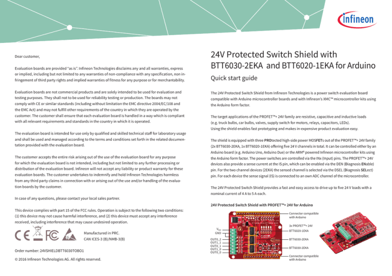
The shield is equipped with three PROtected high-side power MOSFETs out of the PROFET™+ 24V family
(2x BTT6030-2EKA, 1x BTT6020-1EKA) offering five 24 V channels in total. It can be controlled either by an
Arduino board (e.g. Arduino Uno, Arduino Due) or the ARM® powered Infineon microcontroller kits using
the Arduino form factor. The power switches are controlled via the INx (Input) pins. The PROFET™+ 24V
devices also provide a sense current at the IS pin, which can be enabled via the DEN (Diagnosis ENable)
pin. For the two channel devices (2EKA) the sensed channel is selected via the DSEL (Diagnosis SELect)
pin. For each device the sense signal (IS) is connected to an own ADC channel of the microcontroller.
The 24V Protected Switch Shield provides a fast and easy access to drive up to five 24 V loads with a
nominal current of 4 A to 5 A each.
24V Protected Switch Shield with PROFET™+ 24V for Arduino
Connector compatible
with Arduino
VBat
GND
OUT0_2
OUT1_1
OUT0_1
OUT1_0
OUT0_0
3x PROFET™+ 24V
BTT6020-1EKA
BTT6030-2EKA
BTT6030-2EKA
Connector compatible
with Arduino
Getting started
STEP 1
Applications
Features
Choose loads fitting the electrical requirements of the BTT60xx
››Maximum 5 channels
››Current limitation level of 88 A typical
››Nominal load current 5 A per channel
››Drive resistive, capacitive and inductive
››Compatible with Arduino microcontroller
STEP 2
Choose a DC adapter
››Nominal input voltage to the power shield 8 V – 36 V DC
››Functional range 5 V – 48 V forward voltage
loads with PWM or DC
–– 8 ~ 36 V nominal input voltage
(max. 5 ~ 48 V)
–– Nominal current up to 5 A per channel
restricted due to PCB (BTT6020-1EKA
nominal current: 7 A)
–– E.g. truck bulbs, valves, motors, relays ...
Benefits
››Fast and inexpensive prototyping of 24 V
STEP 3
Connect the 24V Protected Switch Shield to
››E.g. XMC1100 boot kit, Arduino Uno R3
NOTE:
Find source code at:
www.infineon.com/shields-for-arduino
load driving
››Load diagnosis with current sense capability
››Overtemperature shut down with latch
behavior
boards and Infineon’s XMC™ microcontroller kits using the Arduino form factor
››Capable of PWM up to 400 Hz
››Driver circuit with logic level inputs
››Diagnosis with current sense
››Protection of load and driver circuit e.g.
against overtemperature, overcurrent, ESD …
Useful links
www.infineon.com/shields-for-arduino
www.infineon.com/profet
www.infineon.com/xmc
Product summary
STEP 4
Program microcontroller board
››Example sketches and projects: www.infineon.com/shields-for-arduino
–– Select your shield (24V Protected Switch Shield)
–– In the documents section download the application example
–– Flash software to microctonroller
Type
Description
Ordering code (OPN)
STEP 5
24V_SHIELD_BTT6030 24V Protected Switch Shield with BTT6030-2EKA 24VSHIELDBTT6030TOBO1
and BTT6020-1EKA for Arduino.
Integrated high-side power switches and part of
the PROFET™+ 24V family. The power transistor
is built by an N-channel vertical power MOSFET
with charge pump in one package (DSO-14).
For reverse current blocking the IPD50P04P4L-11
is used.
Connect the DC adapter to the power shield
BTT6030-2EKA
32 mΩ dual channel smart high-side power
BTT60302EKAXUMA1
switch, embedded in a DSO-14 exposed pad package, providing protective functions and diagnosis.
STEP 6
BTT6020-1EKA
20 mΩ single channel smart high-side power switch, BTT60201EKAXUMA1
embedded in a DSO-14 exposed pad package,
providing protective functions and diagnosis.
IPD50P04P4L-11
P-channel MOSFET intended for reverse battery
protection.
Turn on the power
IPD50P04P4L11ATMA1


