Universal Timer delay circuit 1 sec to 4 hours. 12V 8 amp. Universal
advertisement

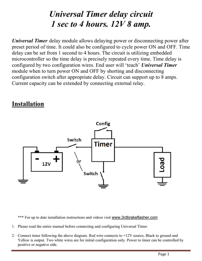
Universal Timer delay circuit 1 sec to 4 hours. 12V 8 amp. Universal Timer delay module allows delaying power or disconnecting power after preset period of time. It could also be configured to cycle power ON and OFF. Time delay can be set from 1 second to 4 hours. The circuit is utilizing embedded microcontroller so the time delay is precisely repeated every time. Time delay is configured by two configuration wires. End user will ‘teach’ Universal Timer module when to turn power ON and OFF by shorting and disconnecting configuration switch after appropriate delay. Circuit can support up to 8 amps. Current capacity can be extended by connecting external relay. Installation *** For up to date installation instructions and videos visit www.3rdbrakeflasher.com 1. Please read the entire manual before connecting and configuring Universal Timer. 2. Connect timer following the above diagram. Red wire connects to +12V source, Black to ground and Yellow is output. Two white wires are for initial configuration only. Power to timer can be controlled by positive or negative side. Page 1 3. Delay power to Load. Follow the steps to configure power delay: Make sure white wires are not shorted. Supply power to timer module. Wait for needed delay and then short two wire wires. Without disconnecting two white wires turn the timer power off. Test the delay by turning the power on. If delay needs to be adjusted repeat steps above. 4. Delay power to Load and then supply power for only specified amount of time. Follow the steps: Make sure white wires are not shorted. Supply power to timer module. Wait for needed delay and then short two wire wires. Keep white wires shorted for the period of time power needs to be supplied to the load. Disconnect white wires and turn the timer power off. Test the delay by turning the power on. If delay needs to be adjusted repeat steps above. 5. Supply power to load for period of time. Follow the steps: Make sure white wires are shorted. Supply power to timer module. Wait for needed delay and then disconnect two wire wires and turn the timer power off. Test the delay by turning the power on. If delay needs to be adjusted repeat steps above. Page 2 6. Cycling power ON and OFF. Follow the steps: Make sure white wires are not shorted. Supply power to timer module. Wait for needed delay and then short two wire wires. Keep white wires shorted for the period of time power needs to be supplied to the load. Disconnect white wires. Short white wires again to tell the timer to repeat configured delay cycle over and over. Turn the timer power off. Test the delay by turning the power on. If delay needs to be adjusted repeat steps above. Warning: When using inductive loads like relays, solenoids or motors connect diode (1N4007) between 86 and 85 to protect from reverse voltage. Extend current capacity be adding external relay. Page 3 Extend voltage and current capacity by adding external relay. Use button to create self latching timer. With a push of the button circuit will supply power to the load until timer delay is expired. Page 4


