SMC-50 Solid-state Smart Motor
Controller for Managing Resistive Loads
William Bernhardt and Richard Anderson, Rockwell Automation
Solid-state contactors (SSCs) are
typically used to control three-phase
resistive heating applications. They are
ideal for these applications because of
the high duty cycle of keeping
temperature at a certain point when
using the standard on-off method of
control. Keeping the hysteresis of the
temperature in check may need
frequent adjustments and a
temperature type controller. Because of
the frequent opening and closure of the
contacts, standard contactors do not last long. Standard contactors have a finite
mechanical life, whereas solid-state devices have a longer useful life and are not as
affected by the mechanical movement.
An SSC uses an analog signal or an on/off signal for full voltage to control the solid-state output to the load. The
analog signal provides more finite sine wave control over a standard on/off control. While the combination of input
control and the SSC performs the control, these devices lack the ability to provide other feedback or protection. For
example, you may need to add external overload protection or external communication devices.
What is the solution?
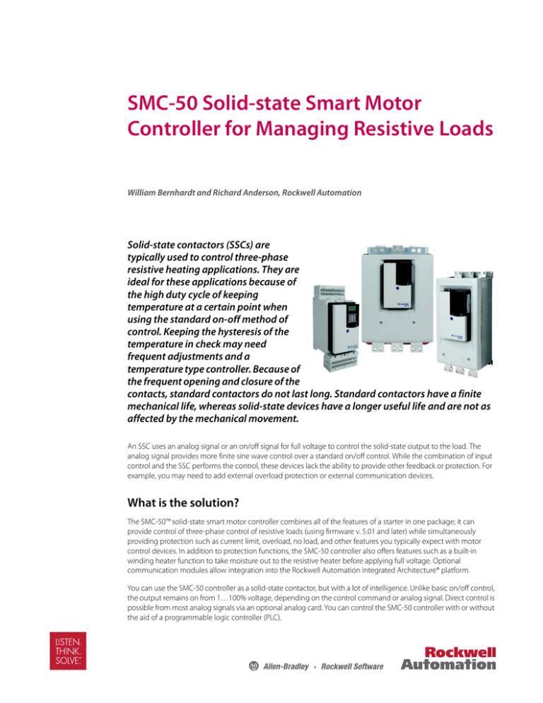
The SMC-50™ solid-state smart motor controller combines all of the features of a starter in one package; it can
provide control of three-phase control of resistive loads (using firmware v. 5.01 and later) while simultaneously
providing protection such as current limit, overload, no load, and other features you typically expect with motor
control devices. In addition to protection functions, the SMC-50 controller also offers features such as a built-in
winding heater function to take moisture out to the resistive heater before applying full voltage. Optional
communication modules allow integration into the Rockwell Automation Integrated Architecture® platform.
You can use the SMC-50 controller as a solid-state contactor, but with a lot of intelligence. Unlike basic on/off control,
the output remains on from 1…100% voltage, depending on the control command or analog signal. Direct control is
possible from most analog signals via an optional analog card. You can control the SMC-50 controller with or without
the aid of a programmable logic controller (PLC).
2 SMC-50 Solid-state Smart Motor Controller for Managing Resistive Loads
What are people doing now?
For some heating applications, people use simple silicon-controlled rectifiers (SCRs) with heat sinks. These typically
use the zero-cross method, discussed further on page 5 . These are SCRs configured in a back-to-back configuration
that provides full cycle control. The back-to-back placement allows control every half cycle.
Figure 1 - Silicon-controlled Rectifier
Figure 2 - RMS Firing Angle (Single-Phase Simplification)
Firing for
100% RMS
Voltage
A temperature controller, such as the Allen-Bradley 900-TC, is typically used to monitor the heating circuit and
control the SCRs for the application. In addition to the temperature controller, you would implement overload
protection to protect the heaters and the SCRs.
Some applications in the field use a combination of solid-state contactors and standard contactors to control the
heater load. In this method, the standard contactors are used to hold the voltage and current at a certain level,
essentially maintaining power at a certain level, and then add a solid-state contactor for the remainder of the
required power. The control switching on and off would come from the SSC. This method adds more components
and wiring to the system because more contactors are needed in addition to the above scenario.
Resistive Loads
Resistive loads typically have no inrush currents. Lamp loads, such as incandescent, halogen, and similar loads, have
inrush of typically 10 …15 times the rated current value, for a short period of time.
Pure resistive loads have a power factor of 1, which is the ratio of real power to apparent power. This means there is
no inrush or high starting currents. However, not all resistive loads are the same. Loads have different hot/cold ratios.
Typically, the lower the ratio, the better the fit for zero cross. The higher the ratio, the better the phase control.
Phase control is the most universal and can be used on lower ratios also. With a lower ratio, you can use other
methods for control, such as zero cross and contactors.
Resistive loads such as nickel-chromium, iron chromium, and aluminum alloy have very little change in resistance as
the temperature changes.
Tungsten, and molybdenum quartz loads can show an increase in resistance during increases in temperatures.
As load elements age, so does resistance; silicon carbide heaters are a good example of this.
SMC-50 Solid-state Smart Motor Controller for Managing Resistive Loads 3
Heaters and Power
It is important to know how much heat the resistive load can dissipate. According to Ohm’s law, the current through
a conductor between two points is directly proportional to the potential difference across the two points.
P=ExI
P = I2 x R
P = E2/R
P = Watts (Power)
E = Volts (Voltage)
I = Amps (Current)
R = Ohms (Resistance)
As stated in the equations above, watts is directly proportional to the square of voltage or current.
The wattage stated on the heater is for use at the rated voltage; when used with reduced voltage, the power is less.
The actual power is the rated power multiplied by the applied voltage to rated voltage
For single-phase applications, the following is true.
Pa = Pr x (Ea/Er)2
Pa = Actual power
Pr = Rated power
Ea= Applied voltage
Er= Rated voltage
Figure 3 shows a 15kW heater with a range of 1…480V AC with the power output increasing as the voltage is
increased.
16000
14000
12000
10000
8000
6000
4000
2000
0
1
19
37
55
73
91
109
127
145
163
181
199
217
235
253
271
289
307
325
343
361
379
397
415
433
451
469
Was
Figure 3 - 15 kW Heater Power vs. Voltage
Volts
15 kW heater rated at 480V
You calculate the AC three-phase power using the following equation:
P = (√3) x E x I x pf
P = Watts (Power)
E = Volts (Voltage)
I = Amps (Current)
pf = power factor
Since resistors have a power factor (pf ) of 1, meaning no inductance, this can be dropped from the formula.
Figure 4 illustrates the two types of resistive balanced loads.
4 SMC-50 Solid-state Smart Motor Controller for Managing Resistive Loads
Figure 4 - Delta- and Wye-connected Resistive Loads
IL
R1
R2
Ep
EL
Ip
IL
R3
Delta
EL = E p
IL = 1.73 x Ip
Ip = IL/1.73
P = ILx EL x 1.73 x PF
W = 1.73 x ILx EL
Ip
R1
Ep
EL
R3
IL
R2
Wye
IL = I p
EL = 1.73 x Ep
Ep = EL/1.73
P = ILx EL x 1.73 x PF
W = 1.73 x ILx EL
SMC-50 Solid-state Smart Motor Controller for Managing Resistive Loads 5
What methods are available?
The core of the control comes from the Silicon-controlled Rectifier (SCR) or thyristor. Controlling the SCRs in different
fashion offers results ranging from zero cross full on to phase control.
For either method, back-to-back SCRs are used to provide conduction for the full sine wave.
Common methods for controlling a resistive load are:
• Zero Cross
• Phase angle switching/firing
Zero cross is when the SCR is started and stopped near zero volts of the AC sine wave. This method is used to
minimize load current when turning on the SCR. In addition, zero cross is the reduction of noise put both on the
power line and what is released in the air. Zero cross is great for constant resistance elements.
One of the common methods using zero cross is burst firing using either a fixed or variable time base. This method
determines the time the cycles are on and off based on the required voltage output. The SCR fires and stops at zero
cross.
Figure 5 - Zero Cross Time Base
ON
OFF
2s
Temperature
Controller
Voltage output
SSR
Enables low-cost, noiseless operation with reduced maintenance requirements.
Phase angle switching allows control of the SCR by firing a portion of each half cycle of the AC sine wave. The
switching on of the SCR depends on the gate signal level applied. This method allows for the capability of firing the
SCR immediately when commanded. The voltage and current output is accurately controlled and is almost
continuous, unlike other methods of control.
The firing turns off at the zero cross, just like zero cross methods. Phase angle switching provides the fastest and
most accurate response time for controlling hysteresis. For loads that have high inrush characteristics, this is the best
method to use, because of the control potential. This method is the most versatile of the resistive starting methods.
It can be used with high hot-to-cold resistance ratios, constant resistance setups, and when resistance increases as
elements age. A heater (or heaters) with changing resistance is the best application for this type of control.
6 SMC-50 Solid-state Smart Motor Controller for Managing Resistive Loads
Figure 6 - Phase Angle Switching Timing Diagram
A key note from Figure 7, comparing using zero cross and not, is that both end on a zero cross. Regardless of when
the stop command is issued, the SCR will conduct until the zero cross point. The SCR is kept on until the output
current is turned off.
Figure 7 - Zero Cross Comparison
~
~
zero cross
voltage
ON
~
~
Output
(load)
OFF
Solid-state contactors with
silicon-controlled rectifiers
or thyristor output and
zero cross function
~
~
~
~
Output
(load)
OFF
ON
~
~
Input
(control)
ON
OFF
Solid-state contactors with
silicon-controlled rectifiers
or thyristor output without
zero cross function
SMC-50 Solid-state Smart Motor Controller for Managing Resistive Loads 7
SMC-50 Controller
The SMC-50 controller is a soft starter that uses phase angle switching/firing using an open loop control in a 3-phase
application. The back-to-back SCR configuration per phase provides control for the full sine wave. Some of the
highlights are detailed in the following paragraphs.
Control: Control is provided from the PLC via communication, human interface module (HIM), direct analog input
with option 150-SM3 analog card, built in DeviceLogix™ outputs or Connected Components Workbench Software.
You can adjust the output from 1…100% in resistive load mode.
Note: Resistive load setting cannot be used on motors!
Auto Tune: The SMC-50 controller does an auto tune for the initial start sequence of the load. The tuning process
identifies pertinent load parameters to provide precise starting control. The auto tune itself can also be forced if
needed, such as situations in which the load has changed.
Resistor Heater: As stated earlier, the SMC-50 controller has a parameter that you can easily set to warm up a
resistor to remove condensation. As with the motor winding heater function, the resistor heater provides low levels
of current to each of the resistor heaters to preheat and help remove condensation or warm the resistor in cold
environments. This is accomplished on a timed basis when a start command is provided.
Continuous Voltage Output: The output remains on as long as the start command is active. This provides smooth
control over the resistive load by continually controlling output of the SMC controller. The range is from 1…100% of
full voltage.
Starting Mode: The SMC-50 controller performs a start similar to the full-voltage start of a motor load. Since the
output is controlled directly, it is directly outputted based on the commanded output, whether that source is analog
or via commanded value.
Current Limit: Provision for current limit throughout the starting and runtime. Essentially, setting the current limit
value assists with keeping the current level to those specified by the application.
Overload Protection: The SMC-50 controller provides the same running protection for resistive loads as it does for
inductive motor loads. You can set the overload alarm between 0…100% to make a user aware if there is an increase
in thermal usage.
Voltage and Current Imbalance: You can set imbalances in voltage and current in both the alarm and fault modes.
Early imbalance detection may prevent damage to the resistive loads.
Real Power Protection: An alarm or fault is triggered if the load wattage is exceeded. You can configure this by
setting the maximum value of the wattage desired. Doing so will assist in preventing damage to the resistive heaters.
The same can be true if real power consumed falls below a certain desired level.
Stopping: The SMC controller stops conducting the SCRs and the load is turned off, with no ramp down. As shown
in Figure 6, the SCRs turn off at zero cross.
Mounting: You can mount the SMC-50 controller with zero clearance on the sides. Top and bottom need a
minimum of 6-inch clearance for proper ventilation when in an enclosure. The SMC-50 controller is fan cooled with
large heat sinks; it is required to be mounted vertically. Further specifications can be found in the SMC-50 controller
user manual for minimum enclosure dimensions.
http://literature.rockwellautomation.com/idc/groups/literature/documents/um/150-um011_-en-p.pdf
8 SMC-50 Solid-state Smart Motor Controller for Managing Resistive Loads
Programming
A few simple parameters need to be set for Resistive Load mode, whether it is used over a communications network
or as a standalone device. Other parameters are available for use and can assist with system monitoring.
The essentials for resistive loads are listed here.
• Parameter 46, Line Voltage
– Set to the actual voltage of the line, not in general terms. For example, if the voltage measures 460 volts,
enter in 460 volts, not 480 volts. The accuracy of the voltage output (parameter 349) depends on the
value entered.
• Parameter 53, Current limit
– Limits the current to the value set in percentage of parameter 78. For example, if parameter 78 is set to
150 A, and parameter 53 is set to 100%, the output (parameter 349) of the SMC is limited to 150 A.
• Parameter 78, Motor FLC
– Set to resistive full load amps at full voltage.
• Parameter 347, Load Type
– Set to resistive load.
• Parameter 348, Reference Source
– Allows you to select the reference source. Output V Ref, Analog Input (Port 7 – 9, Input 1 or 2) or
DeviceLogix Output 1 and 2.
• Parameter 349, Output Voltage Reference
SMC-50 Solid-state Smart Motor Controller for Managing Resistive Loads 9
Wiring
Resistive loads can be wired in Wye or delta configurations. Figure 8 shows an example. As shown, all three phases
have back-to-back SCRs to provide balanced control and full control over the sine wave.
Figure 8 - Resistive Load Wiring Configurations
Conclusion
With the variety of possible resistive loads, the most universal control method is phase angle control, which is the
method used by the SMC-50 controller. Using the phase angle control along with an analog input, whether from a
PLC or directly to the optional analog card on the SMC-50 controller, can provide the resistive load control needed.
Direct control of the output without an analog signal is also possible with commanding the output between
1…100%. The SMC-50 controller could be used to dry out heating resistors before full working voltage is applied,
preventing damage to the element. High hot-to-cold ratios of heaters are well suited for phase angle firing.
All the running protection provided for induction motors is provided with the SMC-50 controller for protection on
heater loads. Unlike using a standard solid-state contactor that needs external overload and protection, protection is
built into the SMC-50 controller in a compact package.
The SMC-50 controller does not require any spacing for ventilation when it is mounted side by side. Sufficient heat
sinks and fans supported by bottom and top air vents keep the controller cool. You need a minimum of 6-inch
clearance on the top and bottom when the controller is in an enclosure.
If you need to use the SMC-50 controller for motor loads, instead of resistive loads, all you need to do is change a
parameter. You do not need to purchase another control module.
Note: Resistive load setting cannot be used on motors.
The SMC-50 controller offers protection, control and versatility for resistive 3-phase loads. The SMC-50 controller has
many ways to configure it, including the optional HIM module, via a communications network, or by using the free
Connected Components Workbench Software™. Connecting with Connected Components Workbench Software
also allows you to directly control the SMC-50 controller for resistive and motor loads.
Rockwell Automation maintains current product environmental information on its website at
http://www.rockwellautomation.com/rockwellautomation/about-us/sustainability-ethics/product-environmental-compliance.page.
Allen-Bradley, Connected Components Workbench, Integrated Architecture, Rockwell Software, Rockwell Automation, SMC, and LISTEN. THINK. SOLVE are trademarks of Rockwell Automation, Inc.
Trademarks not belonging to Rockwell Automation are property of their respective companies.
Publication 150-WP008B-EN-P - February 2016
-Supersedes Publication 150-WP008A-EN-P February 2016
Copyright © 2016 Rockwell Automation, Inc. All rights reserved. Printed in the U.S.A.


