RTM DIN rail mounted miniature electronic timers
advertisement
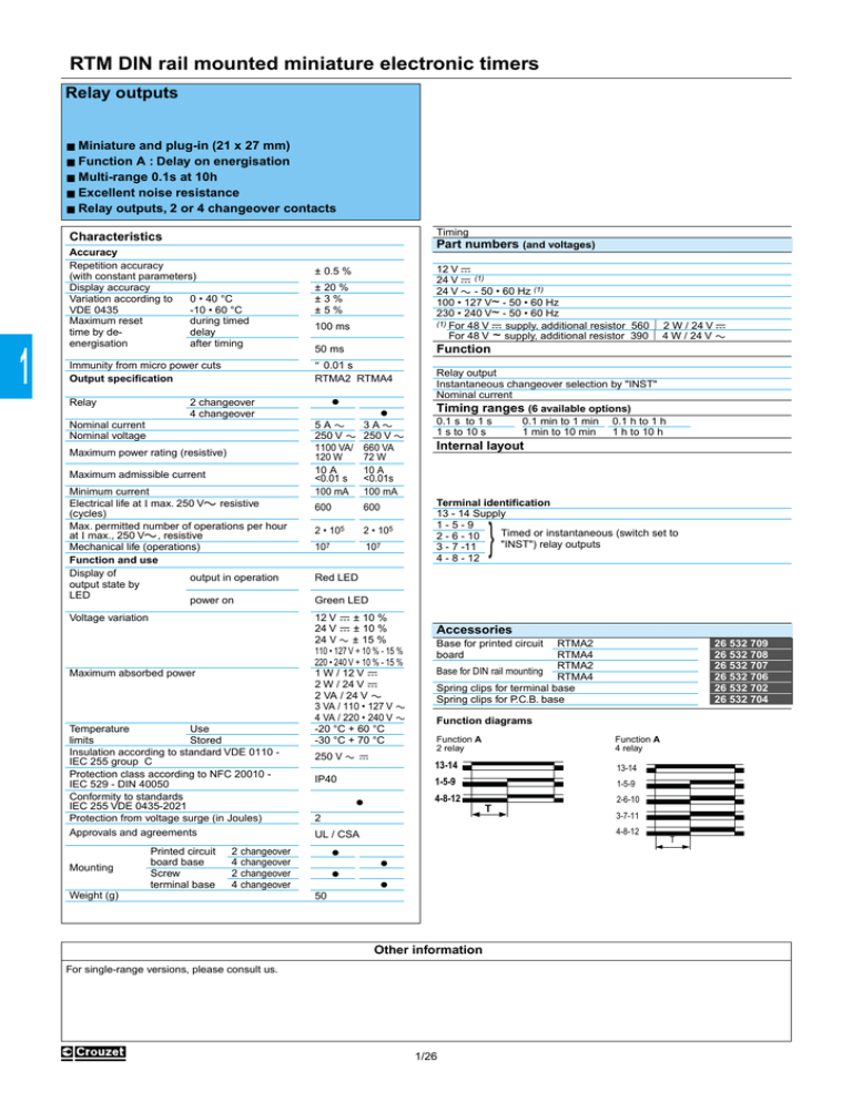
RTM DIN rail mounted miniature electronic timers Relay outputs ■ ■ ■ ■ ■ Miniature and plug-in (21 x 27 mm) Function A : Delay on energisation Multi-range 0.1s at 10h Excellent noise resistance Relay outputs, 2 or 4 changeover contacts Timing Characteristics 1 Accuracy Repetition accuracy (with constant parameters) Display accuracy 0 • 40 °C Variation according to -10 • 60 °C VDE 0435 during timed Maximum reset delay time by deafter timing energisation Nominal current Nominal voltage Maximum power rating (resistive) Maximum admissible current Minimum current Electrical life at I max. 250 Va resistive (cycles) Max. permitted number of operations per hour at I max., 250 Va, resistive Mechanical life (operations) Function and use Display of output in operation output state by LED power on Voltage variation Maximum absorbed power Temperature Use limits Stored Insulation according to standard VDE 0110 IEC 255 group C Protection class according to NFC 20010 IEC 529 - DIN 40050 Conformity to standards IEC 255 VDE 0435-2021 Protection from voltage surge (in Joules) Approvals and agreements Mounting ± 20 % ±3% ±5% 100 ms Function 50 ms ● 2 changeover 4 changeover Printed circuit board base Screw terminal base 12 V c 24 V c (1) 24 V a - 50 • 60 Hz (1) 100 • 127 V~ - 50 • 60 Hz 230 • 240 V~ - 50 • 60 Hz (1) For 48 V c supply, additional resistor 560 Ω 2 W / 24 V c For 48 V ~ supply, additional resistor 390 Ω 4 W / 24 V a ± 0.5 % ≤ 0.01 s RTMA2 RTMA4 Immunity from micro power cuts Output specification Relay Part numbers (and voltages) ● 5Aa 250 V a 1100 VA/ 120 W 10 A <0.01 s 100 mA 3Aa 250 V a 660 VA 72 W 10 A <0.01s 100 mA 600 600 2 • 105 2 • 105 107 107 Relay output Instantaneous changeover selection by "INST" Nominal current Timing ranges (6 available options) 0.1 s to 1 s 0.1 min to 1 min 0.1 h to 1 h 1 s to 10 s 1 min to 10 min 1 h to 10 h Internal layout Terminal identification 13 - 14 Supply 1-5-9 Timed or instantaneous (switch set to 2 - 6 - 10 "INST") relay outputs 3 - 7 -11 4 - 8 - 12 } Red LED Green LED 12 V c ± 10 % 24 V c ± 10 % 24 V a ± 15 % 110 • 127 V + 10 % - 15 % 220 • 240 V + 10 % - 15 % 1 W / 12 V c 2 W / 24 V c 2 VA / 24 V a 3 VA / 110 • 127 V a 4 VA / 220 • 240 V a -20 °C + 60 °C -30 °C + 70 °C 250 V a c IP40 Accessories Base for printed circuit board RTMA2 RTMA4 RTMA2 Base for DIN rail mounting RTMA4 Spring clips for terminal base Spring clips for P.C.B. base Function diagrams Function A 2 relay Function A 4 relay 13-14 13-14 1-5-9 1-5-9 4-8-12 ● 3-7-11 4-8-12 UL / CSA Weight (g) 2-6-10 T 2 2 changeover 4 changeover 2 changeover 4 changeover 26 532 709 26 532 708 26 532 707 26 532 706 26 532 702 26 532 704 T ● ● ● ● 50 Other information For single-range versions, please consult us. 1/26 0.1 s • 10 h 1 RTMA4 88 896 101 88 896 102 88 896 103 88 896 106 88 896 107 Base for printed circuit board RTM A2 - 26 532 709 Mono-function A 2 timed changeover Mono-function A 4 timed changeover 5Aa 3Aa 5 = 3x4,4 = 11,5 1,5 21,5 1 8 + 14 4 9 5 - 13 10 1 6 11 2 7 3 8 2x6,3 25,5 12 13,5 Base for rail mounting RTM A2 - 26 532 707 - 4 RTM A4 - 26 532 706 30 1 4 1 2 3 4 5 8 5 6 7 8 9 12 9 10 11 12 13 14 13 14 (-) (+) 4,1 68 24 (-) (+) 2 - ● - ● ● - - ● ● ● ● ● Spring clips for terminal base 26 532 702 93,5 26 Dimensions 3,5 21 65,5 21 0,55 27 27 R Un 59,5 Spring clips for P.C.B. base 26 532 704 74,5 2,8 0,3 1,2 To order, specify: Standard products 1 H Standard products, non stocked Type 7,5 RTM A4 - 26 532 708 ● 12 = = 21,5 29,5 5 - 13 = 13,5 2 5,3 ● 9 13,2 29,5 ● ● + 14 = 6,5 ● ● 11,5 4,1 5 1,5 21,5 29,5 RTMA2 88 895 101 88 895 102 88 895 103 88 895 106 88 895 107 Accessories 25,5 0.1 s • 10 h Part number Example : RTM miniature electronic timers - 88 895 102 1/27 1
