262726 wiring devices
advertisement
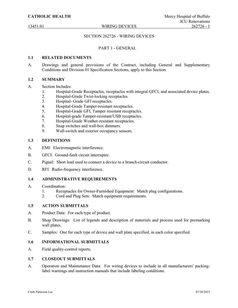
CATHOLIC HEALTH 13451.01 WIRING DEVICES Mercy Hospital of Buffalo ICU Renovations 262726 - 1 SECTION 262726 - WIRING DEVICES PART 1 - GENERAL 1.1 RELATED DOCUMENTS A. Drawings and general provisions of the Contract, including General and Supplementary Conditions and Division 01 Specification Sections, apply to this Section. 1.2 SUMMARY A. Section Includes: 1. Hospital-Grade Receptacles, receptacles with integral GFCI, and associated device plates. 2. Hospital-Grade Twist-locking receptacles. 3. Hospital- Grade GFI receptacles. 4. Hospital-Grade Tamper-resistant receptacles. 5. Hospital-Grade GFI, Tamper resistant receptacles. 6. Hospital-grade Tamper-resistant/USB receptacles. 7. Hospital-Grade Weather-resistant receptacles. 8. Snap switches and wall-box dimmers. 9. Wall-switch and exterior occupancy sensors. 1.3 DEFINITIONS A. EMI: Electromagnetic interference. B. GFCI: Ground-fault circuit interrupter. C. Pigtail: Short lead used to connect a device to a branch-circuit conductor. D. RFI: Radio-frequency interference. 1.4 ADMINISTRATIVE REQUIREMENTS A. Coordination: 1. Receptacles for Owner-Furnished Equipment: Match plug configurations. 2. Cord and Plug Sets: Match equipment requirements. 1.5 ACTION SUBMITTALS A. Product Data: For each type of product. B. Shop Drawings: List of legends and description of materials and process used for premarking wall plates. C. Samples: One for each type of device and wall plate specified, in each color specified. 1.6 INFORMATIONAL SUBMITTALS A. Field quality-control reports. 1.7 CLOSEOUT SUBMITTALS A. Operation and Maintenance Data: For wiring devices to include in all manufacturers' packinglabel warnings and instruction manuals that include labeling conditions. Clark Patterson Lee 07/20/2015 CATHOLIC HEALTH 13451.01 WIRING DEVICES Mercy Hospital of Buffalo ICU Renovations 262726 - 2 1.8 MAINTENANCE MATERIAL SUBMITTALS A. Furnish extra materials that match products installed and that are packaged with protective covering for storage and identified with labels describing contents. 1. Floor Service-Outlet Assemblies: One for every 10, but no fewer than one. 2. Poke-Through, Fire-Rated Closure Plugs: One for every five floor service outlets installed, but no fewer than two. 3. Receptacles: One for each 20 installed, but not less than two PART 2 - PRODUCTS 2.1 MANUFACTURERS A. Manufacturers' Names: Shortened versions (shown in parentheses) of the following manufacturers' names are used in other Part 2 articles: 1. Pass & Seymour/Legrand (Pass & Seymour) or approved equivalent. B. Source Limitations: Obtain each type of wiring device and associated wall plate from single source from single manufacturer. 2.2 GENERAL WIRING-DEVICE REQUIREMENTS A. Wiring Devices, Components, and Accessories: Listed and labeled as defined in NFPA 70, by a qualified testing agency, and marked for intended location and application. B. Comply with NFPA 70. C. Devices that are manufactured for use with modular plug-in connectors may be substituted under the following conditions: 1. Connectors shall comply with UL 2459 and shall be made with stranding building wire. 2. Devices shall comply with the requirements in this Section. 2.3 STRAIGHT-BLADE RECEPTACLES A. All receptacles on the Critical Emergency branch shall be Red in color and have a distinctive label indicating that they are fed from an emergency power source. Receptacles on the Non-Essential and Normal branch shall be white in color. B. Hospital-Grade, Convenience Receptacles, 125 V, 20 A: Comply with NEMA WD 1, NEMA WD 6 Configuration 5-20R, UL 498 Supplement sd, and FS W-C-596. 1. Description: Single-piece, rivetless, nickel-plated, all-brass grounding system. Nickelplated, brass mounting strap. C. Hospital-Grade, USB charging port Convenience Receptacles, 125 V, 20 A: Comply with NEMA WD 1, NEMA WD 6 Configuration 5-20R, UL 498 Supplement sd, and FS W-C-596. 1. Description: Single-piece, rivetless, nickel-plated, all-brass grounding system. Nickelplated, brass mounting strap, (1) 3.1A USB Charging port and (2) Duplex receptacles D. Hospital-Grade, Tamper-Resistant Convenience Receptacles, 125 V, 20 A: Comply with NEMA WD 1, NEMA WD 6 Configuration 5-20R, UL 498 Supplement sd, and FS W-C-596. 1. Description: Labeling shall comply with NFPA 70, "Health Care Facilities" Article, "Pediatric Locations" Section. Clark Patterson Lee 07/20/2015 CATHOLIC HEALTH 13451.01 WIRING DEVICES Mercy Hospital of Buffalo ICU Renovations 262726 - 3 E. Hospital-Grade, Tamper-Resistant with USB charging port Convenience Receptacles, 125 V, 20 A: Comply with NEMA WD 1, NEMA WD 6 Configuration 5-20R, UL 498 Supplement sd, and FS W-C-596. Description: Single-piece, rivetless, nickel-plated, all-brass grounding system. Nickel-plated, brass mounting strap. (1) 3.1A USB Charging port and (2) Duplex receptacles Labeling shall comply with NFPA 70, "Health Care Facilities" Article, "Pediatric Locations" Section. 2.4 GFCI RECEPTACLES A. General Description: 1. Hospital-Grade Straight blade, feed-through type. 2. Comply with NEMA WD 1, NEMA WD 6, UL 498, UL 943 Class A, and FS W-C-596. 3. Include indicator light that shows when the GFCI has malfunctioned and no longer provides proper GFCI protection. B. Hospital-Grade Tamper-Resistant GFCI Convenience Receptacles, 125 V, 20 A: : Comply with NEMA WD 1, NEMA WD 6 Configuration 5-20R, UL 498 Supplement sd, and FS W-C-596. C. Hospital-Grade, GFCI Convenience Receptacles, 125 V, 20 A: Comply with NEMA WD 1, NEMA WD 6 Configuration 5-20R, UL 498 Supplement sd, and FS W-C-596. 2.5 TWIST-LOCKING RECEPTACLES A. Hospital-Grade Single Convenience Receptacles, 125 V, 20 A: Comply with NEMA WD 1, NEMA WD 6 Configuration L5-20R, and UL 498. 2.6 TOGGLE SWITCHES A. All switches on Life-Safety and Critical Emergency branches shall be red in color. B. Comply with NEMA WD 1, UL 20, and FS W-S-896. C. Toggle Switches, 120/277v: Quiet slow make, slow break design, toggle handle with totally enclosed case, rated 20 amp, specification grade. Provide matching two pole, 3 way, and 4 way switches, color: White. D. Retain "Products" Subparagraph and list of manufacturers and products below to require specific products or a comparable product from other manufacturers. E. Key-Operated Switches, 120/277 V, 20 A: 1. Description: Single pole, with factory-supplied key in lieu of switch handle. F. Single-Pole, Double-Throw, Momentary-Contact, Center-off Switches: 120/277 V, 20 A; for use with mechanically held lighting contactors. G. Key-Operated, Single-Pole, Double-Throw, Momentary-Contact, Center-off Switches: 120/277 V, 20 A; for use with mechanically held lighting contactors, with factory-supplied key in lieu of switch handle. 2.7 WALL-BOX DIMMERS A. Dimmer Switches: Modular, full-wave, solid-state units with integral, quiet on-off switches, with audible frequency and EMI/RFI suppression filters. B. Control: Continuously adjustable slider; with single-pole or three-way switching. Comply with UL 1472. Clark Patterson Lee 07/20/2015 CATHOLIC HEALTH 13451.01 WIRING DEVICES Mercy Hospital of Buffalo ICU Renovations 262726 - 4 C. Lutron Diva Designer Series or approved equivalent. 2.8 WALL PLATES A. Single and combination types shall match corresponding wiring devices. 1. Plate-Securing Screws: Metal with head color to match plate finish. 2. Material for Finished Spaces: stainless steel 3. Material for Unfinished Spaces: stainless steel 4. Material for Damp Locations: Thermoplastic with spring-loaded lift cover, and listed and labeled for use in wet and damp locations. B. Wet-Location, Weatherproof Cover Plates: NEMA 250, complying with Type 3R, weatherresistant, die-cast aluminum with lockable cover. 2.9 FINISHES A. Device Color: 1. Wiring Devices Connected to Normal Power System: White unless otherwise indicated or required by NFPA 70 or device listing. 2. Wiring Devices Connected to Emergency Power System: Red B. Wall Plate Color: All cover plates shall be stainless steel. PART 3 - EXECUTION 3.1 INSTALLATION A. Comply with NECA 1, including mounting heights listed in that standard, unless otherwise indicated. B. Coordination with Other Trades: 1. Protect installed devices and their boxes. Do not place wall finish materials over device boxes and do not cut holes for boxes with routers that are guided by riding against outside of boxes. 2. Keep outlet boxes free of plaster, drywall joint compound, mortar, cement, concrete, dust, paint, and other material that may contaminate the raceway system, conductors, and cables. 3. Install device boxes in brick or block walls so that the cover plate does not cross a joint unless the joint is troweled flush with the face of the wall. 4. Install wiring devices after all wall preparation, including painting, is complete. C. Conductors: 1. Do not strip insulation from conductors until right before they are spliced or terminated on devices. 2. Strip insulation evenly around the conductor using tools designed for the purpose. Avoid scoring or nicking of solid wire or cutting strands from stranded wire. 3. The length of free conductors at outlets for devices shall meet provisions of NFPA 70, Article 300, without pigtails. 4. Existing Conductors: a. Cut back and pigtail, or replace all damaged conductors. b. Straighten conductors that remain and remove corrosion and foreign matter. c. Pigtailing existing conductors is permitted, provided the outlet box is large enough. Clark Patterson Lee 07/20/2015 CATHOLIC HEALTH 13451.01 WIRING DEVICES Mercy Hospital of Buffalo ICU Renovations 262726 - 5 D. Device Installation: 1. Replace devices that have been in temporary use during construction and that were installed before building finishing operations were complete. 2. Keep each wiring device in its package or otherwise protected until it is time to connect conductors. 3. Do not remove surface protection, such as plastic film and smudge covers, until the last possible moment. 4. Connect devices to branch circuits using pigtails that are not less than 6 inches in length. 5. When there is a choice, use side wiring with binding-head screw terminals. Wrap solid conductor tightly clockwise, two-thirds to three-fourths of the way around terminal screw. 6. Use a torque screwdriver when a torque is recommended or required by manufacturer. 7. When conductors larger than No. 12 AWG are installed on 15- or 20-A circuits, splice No. 12 AWG pigtails for device connections. 8. Tighten unused terminal screws on the device. 9. When mounting into metal boxes, remove the fiber or plastic washers used to hold device-mounting screws in yokes, allowing metal-to-metal contact. E. Receptacle Orientation: 1. Install ground pin of vertically mounted receptacles down, and on horizontally mounted receptacles to the right. 2. Install hospital-grade receptacles in patient-care areas with the ground pin or neutral blade at the top. F. Device Plates: Do not use oversized or extra-deep plates. Repair wall finishes and remount outlet boxes when standard device plates do not fit flush or do not cover rough wall opening. G. Dimmers: 1. Install dimmers within terms of their listing. 2. Verify that dimmers used for fan speed control are listed for that application. 3. Install unshared neutral conductors on line and load side of dimmers according to manufacturers' device listing conditions in the written instructions. H. Arrangement of Devices: Unless otherwise indicated, mount flush, with long dimension vertical and with grounding terminal of receptacles on top. Group adjacent switches under single, multigang wall plates. I. Adjust locations of floor service outlets and service poles to suit arrangement of partitions and furnishings. 3.2 IDENTIFICATION A. Comply with Section 260553 "Identification for Electrical Systems." B. Identify each receptacle with panelboard identification and circuit number. Use hot, stamped, or engraved machine printing with black-filled lettering on face of plate, and durable wire markers or tags inside outlet boxes. 3.3 FIELD QUALITY CONTROL A. Perform the following tests and inspections with the assistance of a factory-authorized service representative: 1. In healthcare facilities, prepare reports that comply with recommendations in NFPA 99. 2. Test Instruments: Use instruments that comply with UL 1436. Clark Patterson Lee 07/20/2015 CATHOLIC HEALTH 13451.01 3. WIRING DEVICES Mercy Hospital of Buffalo ICU Renovations 262726 - 6 Test Instrument for Convenience Receptacles: Digital wiring analyzer with digital readout or illuminated digital-display indicators of measurement. B. Tests for Convenience Receptacles: 1. Line Voltage: Acceptable range is 105 to 132 V. 2. Percent Voltage Drop under 15-A Load: A value of 6 percent or higher is unacceptable. 3. Ground Impedance: Values of up to 2 ohms are acceptable. 4. GFCI Trip: Test for tripping values specified in UL 1436 and UL 943. 5. Using the test plug, verify that the device and its outlet box are securely mounted. 6. Tests shall be diagnostic, indicating damaged conductors, high resistance at the circuit breaker, poor connections, inadequate fault current path, defective devices, or similar problems. Correct circuit conditions, remove malfunctioning units and replace with new ones, and retest as specified above. C. Test straight-blade convenience outlets in patient-care areas and hospital-grade convenience outlets for the retention force of the grounding blade according to NFPA 99. Retention force shall be not less than 4 oz. D. Wiring device will be considered defective if it does not pass tests and inspections. E. Prepare test and inspection reports. END OF SECTION 262726 Clark Patterson Lee 07/20/2015

